Unleashing the Power of Shaders for Generative Art: An Inside Look at the Creation of 'Shoals'
written by Salviado
Intro
Hi, I'm Salviado and I make art using fragment shaders. I decided to write this article with the intention of shedding some light on the topic and showing how shaders can be used to create beautiful and unique generative art. I'll use my latest work to explain some of the steps in the process of creating a generative piece with shaders.
project name project name project name
What's shader art?
Without going into many technical details, within the different types of shaders, a fragment shader is a program running on the GPU that was originally designed for processing the appearance and behavior of 3D models in real-time and to create graphic effects, among other things. It is responsible for defining the visual properties of the surface of the polygons forming the objects, which are handled by the vertex shader, another type of shader designed for this task. The fragment shader paints the pixels of each polygon by calculating the surface color based on texture, lighting, shadows and so on.
Shader art, popularized by the website Shadertoy, is a form of digital art that utilizes only fragment shaders to create visually stunning images and animations. In this case, there are no predefined 3D models and no vertex data or polygons with the exception of two triangles forming a rectangle which is the canvas painted by the code. The same code runs for every pixel in the canvas, receiving the coordinates of the pixel and other variables called "uniforms", such as a time value used for animations. By using this variables as the input, the program must return the final color of each pixel, using basic math operations and some built-in math functions.
What's raymarching?
Raymarching is a rendering technique used to generate 3D scenes. It involves creating a ray for each pixel, using a 3D vector to specify its direction, and tracing the path of this ray through a virtual 3D space, intersecting them with objects and surfaces. It is computationally expensive, so the use of GPU power is often employed to implement it.
In fragment shaders, raymarching is implemented by defining the 3D objects by using signed distance fields (SDFs). SDFs are mathematical functions that describe the distance between a point in space and the nearest surface. The SDFs are used to calculate the intersection of the ray with the objects, allowing the shading and color of the surface to be calculated. No 3D assets are used, the objects are defined all by code and modeled by math.
There are no built-in raymarching routines of any kind, as fragment shaders weren't designed for this, so the programmer must write the code for it using the vector math capabilities of the language. The code structure for a SDF raymarcher typically includes the following steps:
- Initialize the scene: Define the scene parameters such as camera position, field of view, light parameters and other relevant variables.
- Ray generation: Generate a ray for each pixel in the image to be rendered. This ray represents the path of light that enters the virtual camera lens and travels through the virtual 3D space.
- Intersection testing: Use the SDF function to calculate the distance between the ray and the nearest surface in the 3D scene. This step is performed in a loop, and the loop is continued until the ray intersects with the surface or reaches a maximum iteration count.
- Shading calculation: Once the intersection is found, the code uses the SDF and other information such as surface data and lighting parameters to calculate the shading and coloring.
SDF Modeling
SDF stands for "Signed Distance Field". In computer graphics, the signed distance field defines the distance between a point in space and the nearest surface of the object or surface.
The "signed" aspect of the SDF refers to the fact that the distance can be either positive (outside of the object) or negative (inside of the object). This information is used to determine if a ray intersects with the surface of the object, allowing the object to be rendered in 3D.
This example shows how we can define the SDF of a sphere, and it's also the starting point to model the objects in "Shoals". The language used is GLSL, which stands for "OpenGL Shading Language".
function Sphere(vec3 p, float r)
{
  return length(p)-r;
}
Here we can see that the built-in function used is only "length". In vector mathematics, what this function does is return the length or magnitude of a vector defined in this case by the x, y, z coordinates that the 3D vector called "p" contains. This vector represents the point in space where the ray that went out from the virtual camera to explore the 3D space is located. For a sphere centered at the coordinates 0, 0, 0, the length of this vector defines the distance from the ray to the center of the sphere. By subtracting the value "r" which is also passed as a parameter, the distance is reduced and ends up representing the sphere's radius, since the radius of a sphere is the distance from its surface to its center.
Here is the result of a raymarching implementation with lighting and basic shading that uses this SDF:
One of the benefits of using SDFs is that it's easy to apply transformations to the objects and also to do combinations. In this case, the "sin" trigonometric function was used on the x, y, z coordinates to generate sinusoidal waves and then calculate the length of the resulting vector.
float displacement = length(sin(p * scale));
This value is then added to the sphere's SDF to add displacements and create protuberances:
However, after applying this transform, the SDF is no longer an accurate representation of the surface's distance, but a close estimation. To avoid visual artifacts, the step size of the raymarching loop must be reduced to a lower value. Otherwise, the ray can end up inside the object and we don't want that.
The next step is to "subtract" from the shape another smaller sphere. This can be done by combining two SDF's using the "max" function, which takes in two values as input, and returns the larger of the two values as its output.
float distance = max(sdf1, -sdf2);
The resulting object will only include the bumps:
We are getting closer to the final SDF appearance. Now it's time to apply some rotations. There's no built-in function for this, but the code to return the 2D rotation matrix for a given angle is quite simple:
mat2 rot(float a){
    float s=sin(a),c=cos(a);
    return mat2(c,s,-s,c);
}
First, a rotation is applied on the y axis (by rotating xz values) and it varies along this axis so the result is a "twist" transform. Then the same is done to the x axis. These rotations are applied to the 3D vector "p" just before calculating the SDF.
p.xz*=rot(p.y*0.3);
p.yz*=rot(p.x*0.5);
This is the result:
Finally, the object is combined with a smaller version by utilizing the "min" function to add another signed distance function (SDF) to the previous object. This function returns the minimum value between two SDFs, thereby representing the distance from the current ray position to the surface of the nearest object.
float distance = min(sdf1, sdf2);
And that's all, we have the final SDF of the 3D object, which in this case is quite easy to calculate and helps to understand the process of its creation. More complex 3D scenes could require a lot of calculations and effort.
Coloring
To add color to the objects, I took advantage of the fact that both coordinates and colors are defined by a 3D vector (vec3). This allows me to use the coordinates as if they were a color defined by the combination of red, green, and blue intensity (This is called the RGB color space), which corresponds to the x, y, z values of the vector. Similarly, transformations can be applied to the vec3 color as if they were coordinates. In this case, I used rotations to vary and change the colors in each iteration. I did not include the code as it is a bit complex to understand, but here is the result:
The surfaces of objects also include a reflection, achieved by continuing the advance of the ray in the direction obtained by "reflecting" the vector perpendicular to the collided surface, called the "normal," and calculating a second collision with another object or the background, whose shading is added to the surface color."
Animation
To bring the scene to life, I utilized external variables defined in JavaScript, commonly referred to as "uniforms" as mentioned before. This allows for the transfer of data from the Central Processing Unit (CPU) to the Graphics Processing Unit (GPU). One of these variables is the "time" variable, which tracks the amount of time that has elapsed since the code was executed. Additionally, values from mouse inputs are also utilized. These variables are then used to adjust the angle of the twist rotations and to rotate the camera's position, adding dynamic movement to the scene and interaction:
Background
In the previous sample scenes, if the ray does not collide with any objects, the color of the pixel is set to black. To add a background, I used the same coloring function as the objects but applied it to the coordinates where the ray reached the maximum distance from the camera specified to determine when the raymarching loop should stop if no objects were hit. The coordinates were scaled to adjust the gradients for a smooth and ambient coloring that closely mimics the objects' colors. Additionally, I added a light source through a simple method that calculates the difference in angles between the direction of the ray and the direction of the light. These calculations result in a circular gradient that represents the light source. The shading of the objects is in line with the light position in the scene, creating a consistent overall effect:
Post-processing
It is possible to use multiple fragment shaders in multiple stages, where one shader receives the output from another, allowing for the application of a post-processing effect that has access to all pixels from the previous stage. This is achieved through the use of a type of uniform called sampler2D, which allows a fragment shader to receive an image passed, in this case, from javascript. This shader can then specify the color of each resulting pixel, using the texture2D function to obtain the color of a desired pixel from the incoming texture by specifying the corresponding sampler2D variable and the coordinates of the desired pixel.
vec4 col=texture2D(uniform, coordinates);
The reason why the color is defined by a vec4 rather than a vec3 (i.e. four components), is because the fourth component defines the level of transparency in case the shader is painted over another drawing. This value is also referred to as the "alpha" channel, but it is not utilized in this instance.
So, to add the final touch, I programmed a "bloom" effect. This effect enhances the brightness and radiance of the bright areas in the scene, creating more natural and lifelike lighting. The bloom effect is achieved by capturing the bright parts of the image and applying a blur to them, creating a more radiant and intense appearance. This technique is often used in video games and computer animations to enhance the overall lighting and add a touch of realism.
The other thing the post-processing does is coloring adjustments. They could have been done in the main fragment shader instead, as it doesn't need to access the other pixels from the image like in the bloom effect.
In this image you can see the raw image and the result after applying the effects:
As you can see, the previous example scenes already have the effects applied.
And that's all regarding the creation of the scene within the shader. Now it's time to see how the variations are achieved and the shaders were implemented in the browser.
Variations
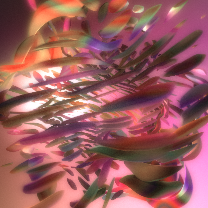
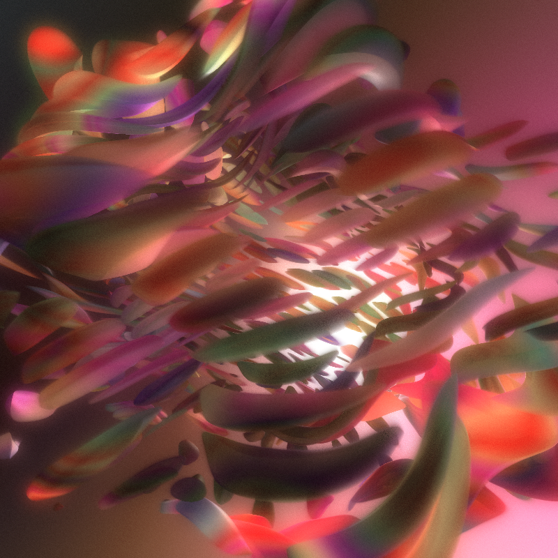
Variations mainly include the colors used, the level of reflectiveness of the material, the intensity of the transformation that deforms the object, its size, and the scale applied to the coordinates used for generating protuberances, resulting in a lesser or greater number of rotating objects and also varying the size of them.
Here is a sample of some of the resulting iterations:
Why do I use p5.js to implement shaders
p5.js is a javascript library that makes it easy to use programming to create graphics and animations in a web browser. It is based on the Processing programming language and provides a simple and intuitive interface for creating visual content, making it accessible to beginners and experienced programmers alike. The library provides a number of built-in functions for drawing shapes, colors, and animations, as well as handling user input and other interactive elements. It is the most used library for creating generative art in fx(hash).
Although I don't use any of the drawing functions included, the library offers an easy way to implement shaders in the browser. It is also very easy to pass uniforms to the shader, including the ability to pass a canvas as a texture simply by using the variable that holds the p5.js canvas.
To load a shader, this code can be used in the preload() function:
shader = loadShader("base.vert", "shader.frag");
shader.frag is the fragment shader, while base.vert is a basic vertex shader that defines the rectangle that the fragment shader will paint.
Then, in the draw function, this code will set the uniforms and paint the shader into the canvas:
  shader.setUniform("time", millis()/1000);
  shader.setUniform("resolution", [width,height]);
  shader(sh);
  res.rect(0,0,width,height);
Notes on shader art in fx(hash)
I've noticed that shader art isn't too popular on fx(hash), especially animated works. I believe that shader programming is often misunderstood. Talking to some people about it, it's common to find that people believe shaders are an easier way to create generative art compared to using purely p5.js's drawing functions or other methods for making graphics in the browser. The way 3D scenes are created is also misconstrued, as some think it's achieved through pre-generated assets just manipulated by code or that there are built-in functions for creating 3D objects out of the box. Also I've encountered some people who hold the belief that it's a versatile library capable of simplifying a majority of tasks. I think perhaps these are reasons why the art of shaders is underrated even though all of the above is exactly the opposite of what shader art actually is. As I mentioned before, fragment shaders are programs that run for each pixel on the canvas, always the same code that simply receives the coordinates of that pixel and specifies what color it is. This has to be achieved using numbers, operators, and some included mathematical functions. There's no easy way even to draw a circle in the center of the canvas. There are no built-in functions to do this, like in p5.js. One has to mathematically calculate whether the pixel is inside the circle or not and then specify the color based on this.
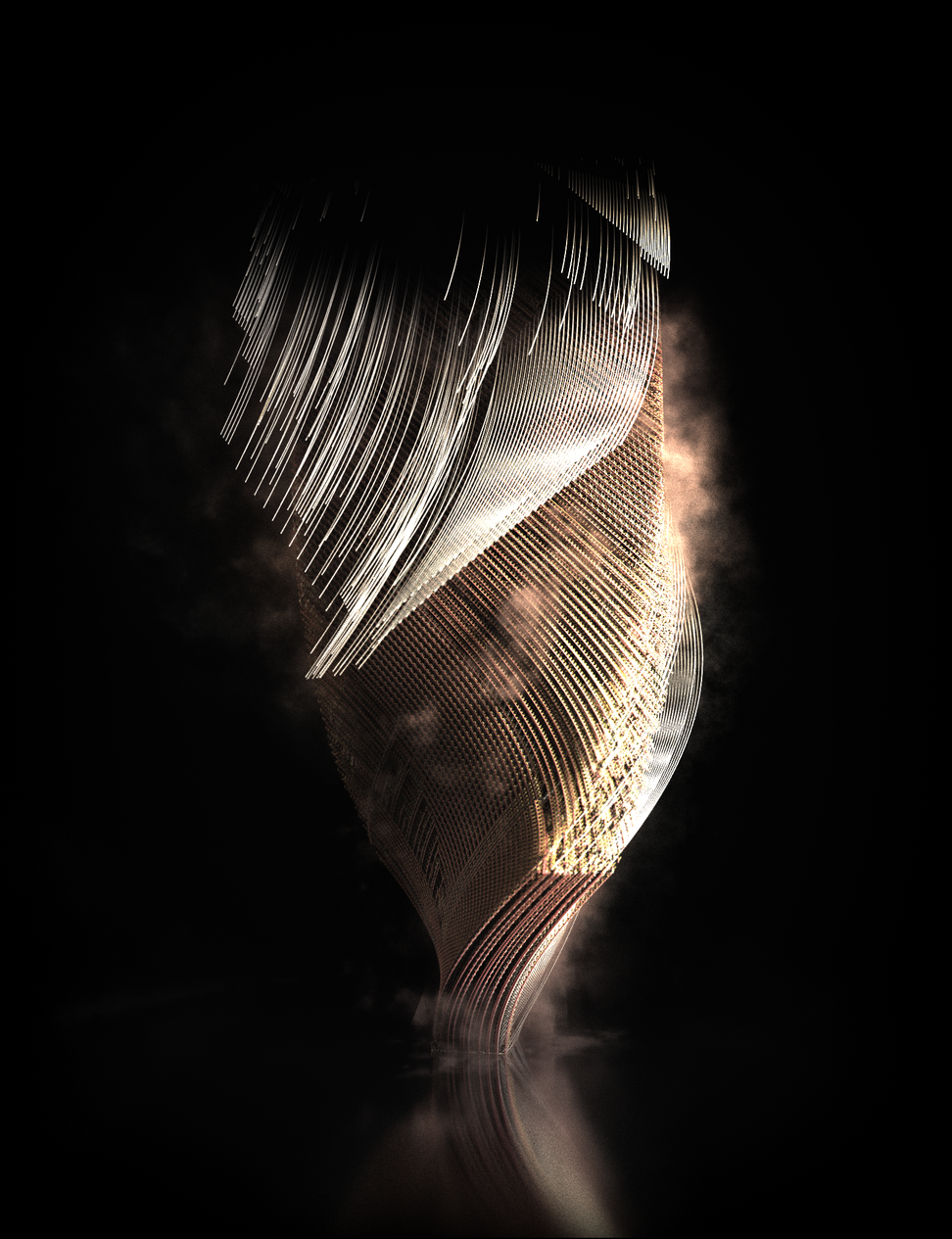
One of my reasons for writing this article is to raise awareness and increase appreciation for the art of shaders. Despite the misperceptions surrounding this form of graphics, there have been several successful shader projects. Artist Monotau is a prime example of excellence in this field, and I am grateful to own an iteration of his latest work.
project name project name project name
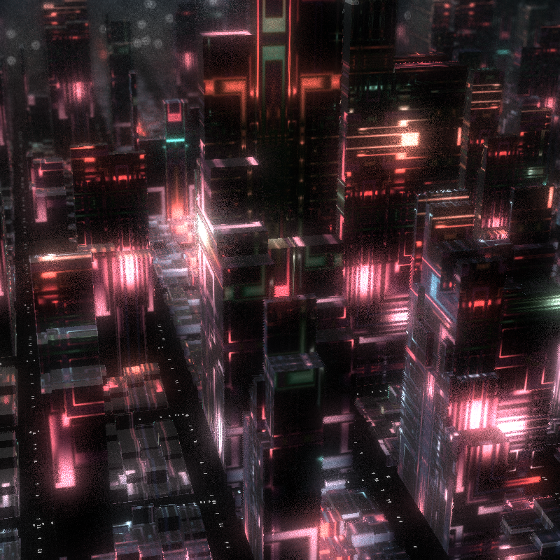
Another artist who almost exclusively uses shaders for his work is Kali, who has received significant recognition from the community. This is his latest work to date, a lovely raymarched scene of a cyberpunk city:
project name project name project name
There are several other artists who use shaders and I hope that we will continue to see more and more of them in the future!


