O B S C V R V M - Algorithms and Code
written by {protocell:labs...
Codebase overview
/*

     ██████╗  ██████╗  ███████╗  ██████╗ ██╗   ██╗ ██████╗  ██╗   ██╗ ███╗   ███╗
    ██╔═══██╗ ██╔══██╗ ██╔════╝ ██╔════╝ ██║   ██║ ██╔══██╗ ██║   ██║ ████╗ ████║
    ██║   ██║ ██████╔╝ ███████╗ ██║      ██║   ██║ ██████╔╝ ██║   ██║ ██╔████╔██║
    ██║   ██║ ██╔══██╗ ╚════██║ ██║      ╚██╗ ██╔╝ ██╔══██╗ ╚██╗ ██╔╝ ██║╚██╔╝██║
    ╚██████╔╝ ██████╔╝ ███████║ ╚██████╗  ╚████╔╝  ██║  ██║  ╚████╔╝  ██║ ╚═╝ ██║
     ╚═════╝  ╚═════╝  ╚══════╝  ╚═════╝   ╚═══╝   ╚═╝  ╚═╝   ╚═══╝   ╚═╝     ╚═╝


          O B S C V R V M  |  { p r o t o c e l l : l a b s }  |  2 0 2 2
*/
Codebase is available either directly through inspecting the sources while viewing the token in live mode (Developer Tools in your browser -> Sources) or on our {protocell:labs} GitHub repository. You can also run the live demo hosted on GitHub and get a random iteration every time you refresh the page. Most important files in the codebase, and the ones we'll be primarily focusing on, are as follows:
-
index.html// main webpage file, loads all JavaScript modules and handles the webpage itself -
main.js// main JavaScript file that connects all others, the start for generation of geometry -
utils.js// defines all custom functions -
params.js// defines parameters of the token -
lattice_generation.js// generates data for the lattice geometry (higher-level) -
subdivision.js// custom functions and classes for subdivision used for lattice generation (lower-level) -
three.js// standard JavaScript library for WebGL, 3D geometry creation and manipulation
As with any token on fxhash, the code starts with index.html, although nothing really interesting is happening there. All JS (JavaScript throughout this article) modules are loaded, fxrand() function for introducing randomness is defined, as well as the splash screen (shown during loading). O B S C V R V M really starts with main.js, which is executed at the bottom of index.html.
NOTE ON RANDOMNESS: When coding pieces for fxhash, we cannot (in most cases) use Math.random() function. This is because it is impossible to set a seed for it, so it will always return a random result. Randomness for fxhash tokens needs to be "seeded" to always give us the same result for the given seed. Fxhash is providing its own PRNG function for that called fxrand(). If you run your code locally, this function will behave like Math.random(), but a seed for it will be set to the transaction hash when the token is minted. In our code, we renamed this function to gene(), so anywhere where you see gene(), remember that it's just fxrand() in disguise. This function is returning a random number between 0 and 1 with uniform distribution, same as Math.random(). We do this renaming in utils.js like this:
//FXHASH random function for specific implimentation
gene = fxrand;
project name project name project name
Defining piece composition
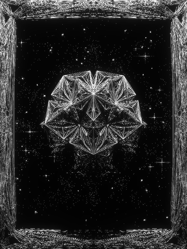
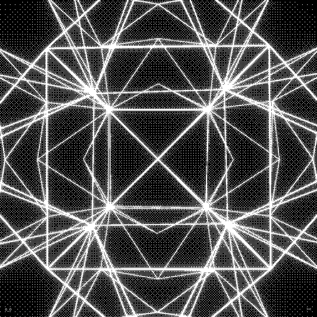
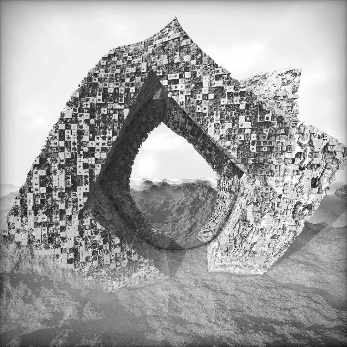
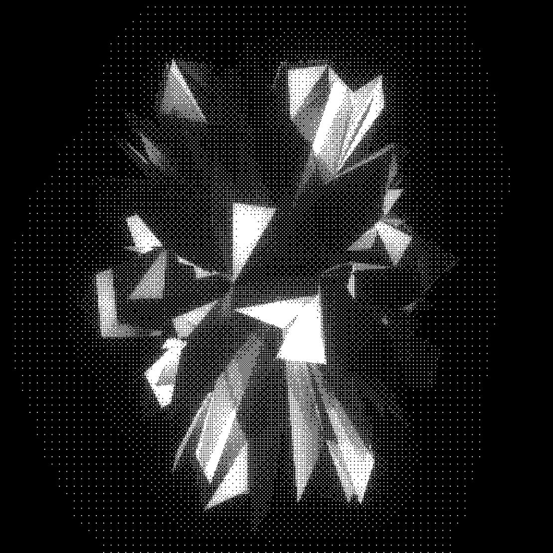
Every O B S C V R V M piece is a spatial composition consisting of:
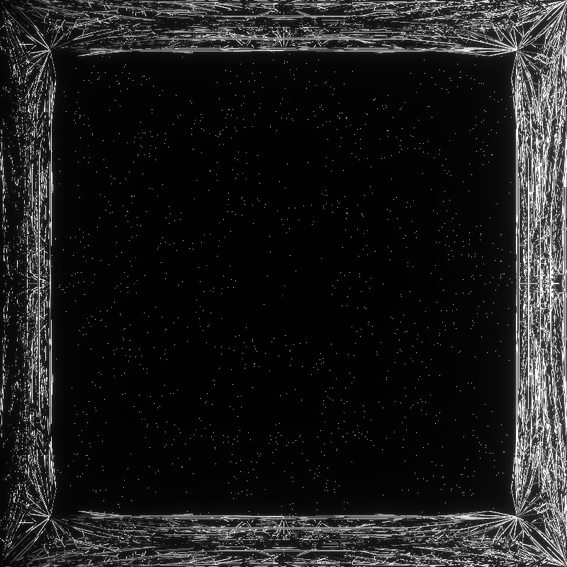
- a frame
- a central lattice
- a background
These three elements are layered in space like theater scenography. Parameters for this composition are generated at the top of main.js file.
// COMPOSITION - generate parameters for the composition of the piece
// all input parameters are optional, they will be chosen at random if not passed into the function
composition_params = generate_composition_params();
Function generate_composition_params() is defined in params.js. It generates everything needed to define the composition randomly using defined probabilities, then stores all of these variables into a single object composition_params. Let's have a look what ends up in it:
// this object will hold all of our composition parameters which we can unpack when we need them
var composition_params = {
aspect_ratio: aspect_ratio, // 0.75, 1.0, 1.5
frame_type: frame_type, // 'none', 'narrow', 'dominating'
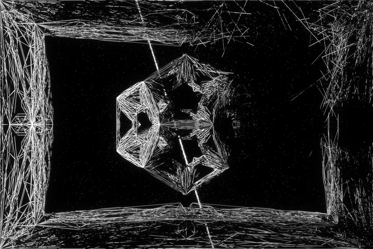
center_piece_type: center_piece_type, //'none', 'plane', 'triangle', 'double_triangle', 'tetrahedron', 'pentagon', 'octahedron', 'hexahedron', 'dodecahedron', 'station_h', 'station_t', 'station_o', 'station_d'
center_piece_factor: center_piece_factor, // default is 0.5, can also be 0.65 or 0.75 for exploded lattices
explosion_type: explosion_type, // 0 (pristine), 1, 2, 3, 4 (sliced), 5, 6 (pierced)
light_source_type: light_source_type, // 'west', 'east', 'north', 'south'
explosion_center_a: explosion_center_a, // THREE.Vector3()
explosion_center_b: explosion_center_b, // THREE.Vector3()
celestial_object_types: celestial_object_types, // 'none', 'comet', 'eclipse', 'ultra eclipse', 'moon', 'planet', 'orbit', 'meteor shower', 'quasar', 'nova', 'rapture', 'nebula', 'constellation'
feature_dimension: feature_dimension, // 'portrait', 'square', 'landscape'
feature_frame: feature_frame, // 'none', 'narrow', 'dominating'
feature_primitive: feature_primitive, //'none', 'plane', 'triangle', 'star', 'tetrahedron', 'pentagon', 'octahedron', 'hexahedron', 'dodecahedron', 'station'
feature_state: feature_state, // 'pristine', 'sliced', 'pierced'
feature_celestial: feature_celestial // 'none', 'comet', 'eclipse', 'ultra eclipse', 'moon', 'planet', 'orbit', 'meteor shower', 'quasar', 'nova', 'rapture', 'nebula', 'constellation'
}
Parameters like token aspect ratio (square, portrait, landscape), frame type (none, narrow, dominating), center piece type (none, plane, triangle, octahedron, hexahedron...), explosion type (pristine, sliced, pierced), type of celestial object appearing in the background, and the names of actual features used by fxhash site for the token, are all defined here. As all of these parameters are defined in a similar way inside generate_composition_params(), we can look at a single one to understand the process of selection guided by predefined probability. Let's have a look at how center_piece_type is defined:
if (center_piece_type == undefined) {center_piece_type = gene_weighted_choice(allel_center_piece_type);}
Ok, so if center_piece_type is not already passed into the function via input parameter, it is undefined and needs to be created on the spot (this mechanic enables us to override the parameter by passing it into the function before). All parameters in the collection are chosen the same way, by using gene_weighted_choice() function on an allele (this term comes from biology and refers to a variation of the same sequence of nucleotides at the same place on a long DNA molecule, basically the "options list" for the nucleotide sequence). The gene_weighted_choice() function is defined in utils.js and it looks like this:
// input data of the format [[element, probability], [element, probability]...]
function gene_weighted_choice(data){
  let total = 0;
  for (let i = 0; i < data.length; ++i) {
      total += data[i][1];
  }
  const threshold = gene() * total;
  total = 0;
  for (let i = 0; i < data.length - 1; ++i) {
      total += data[i][1];
      if (total >= threshold) {
          return data[i][0];
      }
  }
  return data[data.length - 1][0];
}
To understand what it does, we have to look at the allele variable as well. All alleles are defined in params.js. Here is the allele for center_piece_type which we are trying to define:
// allel entry has the form [element, probability]
const allel_center_piece_type = [
  ['none', 10], // 10% probability
  ['plane', 15], // 15% probability
  ['triangle', 15], // 15% probability
  ['double_triangle', 5], // 5% probability
  ['tetrahedron', 5], // 5% probability
  ['pentagon', 10], // 10% probability
  ['octahedron', 10], // 10% probability
  ['hexahedron', 10], // 10% probability
  ['dodecahedron', 10], // 10% probability
  ['station_h', 3], // 3% probability
  ['station_t', 3], // 3% probability
  ['station_o', 2], // 2% probability
  ['station_d', 2] // 2% probability
];
Alleles are just a list containing pairings (itself a short list) of two values of the form [element, probability]. The first entry is the actual element we want to choose or retrieve, the second value is the probability for choosing that element. To get the actual probability, we have to divide the element's probability with the sum of all probabilities in the allele. This means we are flexible and don't need to ensure that probabilities add up to 1 or 100, rather they can add up to any number. If the probability values for all the elements are the same (say, 1) then the elements have an equal probability to be chosen when passed into gene_weighted_choice() function. For readability and control, we always made sure these probabilities actualy add up to 100. This way they directly represent percentages (in our example above, 'none' will be chosen with 10% probability, 'plane' with 15% etc.) To conclude, if we call center_piece_type = gene_weighted_choice(allel_center_piece_type); like shown above, center_piece_type will be assigned a random element from the allele list based on its predefined probability. In this case, it will be a simple string variable which we can use later to define the type of primitive we need to use for the central lattice.
Now back into generate_composition_params() function. After we define center_piece_type, we need to define certain exceptions and overrides as well:
// EXCEPTIONS AND OVER-RIDES
// we never want to have a completely empty piece, also if frame is empty, there is no explosion
if (center_piece_type == 'none') {frame_type = 'narrow'; explosion_type = 0;}
// first choice priority for celestial object types
if (center_piece_type == 'none') {celestial_object_types = gene_weighted_choice(allel_celestial_object_types_empty);}
// make triangle bigger for horizontal and vertical explosions
if (center_piece_type == 'triangle' && (explosion_type == 1 || explosion_type == 2 || explosion_type == 3 || explosion_type == 4)) {center_piece_factor = 0.75;}
// make triangle bigger for point explosions
if (center_piece_type == 'triangle' && (explosion_type == 5 || explosion_type == 6)) {center_piece_factor = 0.65;}
// make octahedron bigger for explosions
if (center_piece_type == 'octahedron' && explosion_type != 0) {center_piece_factor = 0.65;}
// make tetrahedron bigger for explosions
if (center_piece_type == 'tetrahedron' && explosion_type != 0) {center_piece_factor = 0.75;}
// make dodecahedron bigger for explosions
if (center_piece_type == 'dodecahedron' && explosion_type != 0) {center_piece_factor = 0.75;}
Turns out center_piece_type has the most exceptions of all the parameters here. We defined these through many rounds of testing. For example, when the central piece is defined as 'none', we will default to having no explosions and select celestial objects from a different allele than with standard pieces. So, depending on what is decided for the center piece, probabilities for celestial objects will also change. This makes calculating the final probabilities of features a bit harder, but it's also a way to "curate" the algorithm to produce some outputs more than the others. Also, it makes some combinations impossible to appear , for example any type of explosion with an empty frame.
Now that the center_piece_type is selected, we need to turn it into an fxhash feature so it can be displayed together with the token on the website. Not all token parameters will become features, as there are far too many of them. Additionally, names of features might be different than just a printout of the parameter value. We define these carefully using a simple conditional statement:
// options for the center_piece_type are 'none', 'plane', 'triangle', 'double_triangle', 'tetrahedron', 'pentagon', 'octahedron', 'hexahedron', 'dodecahedron', 'station_h', 'station_t', 'station_o', 'station_d'
if (center_piece_type == 'double_triangle') {feature_primitive = 'star';}
else if (center_piece_type == 'station_h' || center_piece_type == 'station_t' || center_piece_type == 'station_o' || center_piece_type == 'station_d') {feature_primitive = 'station';}
else {feature_primitive = center_piece_type;}
In general, the string for the center_piece_type will just be taken as the name of the feature_primitive, except in few cases where we want to have a different name or group many types under a single feature name for simplicity. All feature names will be passed to the fxhash website with the following code defined in main.js.
//////FXHASH FEATURES//////
window.$fxhashFeatures = {
  'Dimension': feature_dimension, // 'portrait', 'square', 'landscape'
  'Frame': feature_frame, // 'none', 'narrow', 'dominating'
  'Primitive': feature_primitive, //'none', 'plane', 'triangle', 'star', 'tetrahedron', 'pentagon', 'octahedron', 'hexahedron', 'dodecahedron', 'station'
  'State': feature_state, // 'pristine', 'sliced', 'pierced'
  'Celestial': feature_celestial // 'none', 'comet', 'eclipse', 'ultra eclipse', 'moon', 'planet', 'orbit', 'meteor shower', 'quasar', 'nova', 'rapture', 'nebula', 'constellation'
};
Aside from showing them on the website, we can also print them to the token console from main.js, together with some other useful information like this:
console.log('%cTOKEN FEATURES', 'color: white; background: #000000;', '\n',
            'Dimension -> ' + feature_dimension, '\n',
            'Frame     -> ' + feature_frame, '\n',
            'Primitive -> ' + feature_primitive, '\n',
            'State     -> ' + feature_state, '\n',
            'Celestial -> ' + feature_celestial, '\n');
Neat. Looking back to generate_composition_params() function in params.js, it finishes by defining all composition parameters and token features, and packs them all into a JS object composition_params which the function returns. In main.js we could for example use center_piece_type by calling composition_params['center_piece_type'], but we opted for unpacking all parameters and using them in the code as globals. This way we can write them in their shorter form, although there are certainly arguments against this approach as well (it worked for us though). This unpacking of values from an array or an object and turning them into global variables is called destructuring. We perform it in main.js right after we call composition_params = generate_composition_params();
// destructuring - unpacking parameters we need in main.js and turning them into globals
var { aspect_ratio, frame_type, center_piece_type, center_piece_factor, explosion_type, light_source_type, explosion_center_a, explosion_center_b, celestial_object_types, feature_dimension, feature_frame, feature_primitive, feature_state, feature_celestial } = composition_params;
Defining lattice parameters
Now all parameters for the composition are available by their names which we defined in params.js. We'll skip the generation of the frame (step nr. 1. in creating a composition) and jump to generating the center piece, which is also a lattice geometry made out of cylinders. The frame in step 1. is created in the same way, except some parameters of the lattice are manually constrained so the lattice always looks like a frame. The lattice for the center piece is defined with this code below:
// LATTICE 2 - CENTER, random primitive, smaller size
if (center_piece_type != 'none') {
  // all input parameters are optional, they will be chosen at random if not passed into the function
  lattice_params = generate_lattice_params(center_piece_type);
  lattice_params['start_bounds'] = lattice_params['start_bounds'] * center_piece_factor;
  gData = generate_lattice(lattice_params);
  gDatas.push(gData);

  // generate another triangle with same parameters but rotated 180 degrees
  if (center_piece_type == 'double_triangle') {
    lattice_params['start_rot'] = lattice_params['start_rot'] == -30 ? 150 : -30;
    gData = generate_lattice(lattice_params);
    gDatas.push(gData);
  }

} else if (center_piece_type == 'none') {
  // in this case we are not drawing a center piece at all
}
Again, a simple conditional statement. The main purpose here is to generate gDatas, an array containing our custom gData object containing everything we need to define a lattice geometry. If the center_piece_type is defined as 'none', we just jump out of the conditional and gDatas remains empty, so no lattice will be drawn later. For 'double_triangle' we need to draw two lattices, so this case is specially defined. Otherwise, the standard way of generating gData is to first generate lattice_params using generate_lattice_params() function, then pass it to generate_lattice(). gData is added to the gDatas list, as each composition often includes more than one lattice (a frame and a center piece). In its simplest form, this is how we could use it:
// simplest way of generating gData for lattice creation
// all input parameters are optional, they will be chosen at random if not passed into the function
lattice_params = generate_lattice_params(center_piece_type);
gData = generate_lattice(lattice_params);
gDatas.push(gData);
Let's look at generate_lattice_params() function first. It is defined in params.js and in its structure it is very similar to generate_composition_params(). It generates all parameters needed for drawing the lattice and stores them into an lattice_params object.
// this object will hold all of our lattice parameters which we can unpack when we need them
var lattice_params = {
  start_bounds: start_bounds, // size of the primitive that is subdivided
  primitive: primitive, // starting primitive for the subdivision
  deform_type: deform_type, // non-uniform scaling is available for some primitives, not used in O B S C V R V M
  position: position, // absolute position of the lattice, defaults to the world origin
  stage: stage, // number of iterations for the subdivision
  double_sided: double_sided, // faces can be double-sided, which doubles the geometry and steps
  start_rot: start_rot, // some primitives can have a different starting rotation
  sub_rules: sub_rules, // for each stage, we define one of two subdivision rules - rule pyramid or rule tapered
  mod_rules: mod_rules, // can be used to create irregular subdivision, not used in O B S C V R V M
  extrude_face: extrude_face, // for each stage, how far is the face extruded while applying subdivision rules (can also be negative)
  extrude_face0: extrude_face0, // same as extrude_face but different values, used for transformation, not used in O B S C V R V M
  contract_middle: contract_middle, // for each stage, if the rule is rule tapered, how much is the face contracted
  leave_middle: leave_middle, // for each stage, if the rule is rule tapered, is the middle face left or removed
  flip_dash: flip_dash, // for the pattern of dashed mesh lines, not used in O B S C V R V M
  steps: steps, // used to control animation for transformation, not used in O B S C V R V M
  transformation_type: transformation_type, // used to control animation for transformation, not used in O B S C V R V M
  transformation_index: transformation_index, // used to control animation for transformation, not used in O B S C V R V M
  triangulate: triangulate, // during subdivision, if the face is not a triangle, should it first be triangulated or not
}
As with the generate_composition_params() function, we will not go through every parameter, rather we will focus only on the primitive to demonstrate how the function is defining it. Notice we are passing center_piece_type value into generate_lattice_params() , which means it will be taken as a type parameter inside it. This type can simply be taken as a value for the primitive parameter (exceptions will be handled later).
if (type == undefined) {var primitive = gene_weighted_choice(allel_primitive);}
else {var primitive = type;}
Only if it would not be passed into the function, we would choose a value for it from allel_primitive using gene_weighted_choice() function. But in our case, it will always be defined as we already chose the primitive when choosing the center_piece_type. primitive parameter is used throughout the function to define other aspects of the lattice, here are some of them:
var start_bounds = get_start_bounds(primitive);
if (stage == undefined) {var stage = gene_weighted_choice(get_allel_stage(primitive));}
var double_sided = get_double_sided(primitive);
var start_rot = get_start_rot(primitive); // this parameter is only used with triangle and pentagon primitives
var extrude_bounds = get_extrude_bounds(primitive);
All of these "get" functions take primitive as an input and return another parameter. For example, get_extrude_bounds() returns a number which is later used to define bounds for face extrusion distance when performing subdivision of the lattice faces. These bounds are empirically tested to produce the most varied outputs for each primitive:
function get_extrude_bounds(primitive) {
  var extrude_bounds;
  if (primitive == 'plane') {extrude_bounds = 100;}
  else if (primitive == 'triangle') {extrude_bounds = 100;}
  else if (primitive == 'tetrahedron') {extrude_bounds = 50;}
  else if (primitive == 'pentagon') {extrude_bounds = 100;}
  else if (primitive == 'octahedron') {extrude_bounds = 50;}
  else if (primitive == 'hexahedron') {extrude_bounds = 50;}
  else if (primitive == 'dodecahedron') {extrude_bounds = 100;}
  else if (primitive == 'station_h') {extrude_bounds = 25;}
  else if (primitive == 'station_t') {extrude_bounds = 25;}
  else if (primitive == 'station_o') {extrude_bounds = 25;}
  else if (primitive == 'station_d') {extrude_bounds = 25;}
  return extrude_bounds
}
In generate_lattice_params() function, extrude_bounds is used in the following way:
// range, factors of range reduction for every stage
var extrude_face = get_extrude_face([-extrude_bounds, extrude_bounds], [1.0, 0.5, 0.5, 0.25, 0.25, 0.25, 0.25, 0.25]);
The important thing to understand here is that this makes lattice parameters interdependent. They are linked in various ways and the order of their definition matters, as we start with the most independent parameters (primitive) and end with more dependent ones (extrude_face).
The last thing to consider inside generate_lattice_params() function are special cases, namely station primitives. There are four of them and although they have their own name, they are in fact based on some other, already defined primitive. These special cases are defined at the end, essentially overriding parameters which were defined above. Here is an example of how parameters for 'station_t' (station based on tetrahedron) are defined:
if (type == 'station_t') {
  primitive = 'tetrahedron';
  sub_rules[0] = 1; // force rule tapered for the first iteration
  extrude_face[0] = gene() < 0.75 ? 200 : 1000; // first extrusion will be very large
  contract_middle[0] = gene() < 0.75 ? 0.01 : 0.95; // small contraction of the first face creates long "arms" at the side of the cube
}
Generating the lattice
After special cases are defined, all lattice parameters are packed into lattice_params object and returned back to main.js to be passed into generate_lattice() function, which returns gData object.
gData = generate_lattice(lattice_params);
Finally, we have everything we need to define lattice geometry, now we just have to generate it. lattice_generation.js is where this happens, and this file is so short that we can just show it here in full.
// LATTICE GENERATION STEPS

//subdivision rule declaration
rule_pyramid = new RulePyramid_v2();
rule_tapered = new RuleTapered_v2();

function generate_lattice(lattice_params) {

    // object destructuring - this will unpack all values from the dict and assign them variable names according to their keyes
    var { primitive, stage, start_bounds, double_sided, start_rot, deform_type, position, sub_rules, mod_rules, extrude_face, extrude_face0, contract_middle, leave_middle, triangulate } = lattice_params;

    var start_mesh;

    if (primitive == 'plane') {
    start_mesh = new Plane(position.x, position.y, position.z, start_bounds*deform_type[0], start_bounds*deform_type[1], double_sided)
    } else if (primitive == 'triangle') {
    start_mesh = new Triangle(position.x, position.y, position.z, start_bounds * 0.5, double_sided, start_rot)
    } else if (primitive == 'pentagon') {
    start_mesh = new Pentagon(position.x, position.y, position.z, start_bounds * 0.5, double_sided, start_rot)
    } else if (primitive == 'hexahedron') {
    start_mesh = new Hexahedron(position.x, position.y, position.z, start_bounds*deform_type[0], start_bounds*deform_type[1], start_bounds*deform_type[2], double_sided)
    } else if (primitive == 'dodecahedron') {
    start_mesh = new Dodecahedron(position.x, position.y, position.z, start_bounds * 0.5, double_sided)
    } else if (primitive == 'tetrahedron') {
    start_mesh = new Tetrahedron(position.x, position.y, position.z, start_bounds * 0.75, double_sided)
    } else if (primitive == 'octahedron') {
    start_mesh = new Octahedron(position.x, position.y, position.z, start_bounds, start_bounds, start_bounds, double_sided)
    }

    var lattice_mesh = start_mesh.get_mesh();
    var lattice_mesh_target = start_mesh.get_mesh(); //JSON.parse(JSON.stringify(lattice_mesh)); //Deep Copy

    for (var i = 0; i < stage; i++) {
        if (sub_rules[i] == 0) {
            // PYRAMID
            lattice_mesh = rule_pyramid.replace(lattice_mesh, extrude_face[i], mod_rules[i]);
            lattice_mesh_target = rule_pyramid.replace(lattice_mesh_target, extrude_face0[i], mod_rules[i]);
        } else {
            // TAPERED PYRAMID
            lattice_mesh = rule_tapered.replace(lattice_mesh, contract_middle[i], extrude_face[i], leave_middle[i], mod_rules[i])
            lattice_mesh_target = rule_tapered.replace(lattice_mesh_target, contract_middle[i], extrude_face0[i], leave_middle[i], mod_rules[i])
        }
    }

    return mesh_to_gData(lattice_mesh, lattice_mesh_target, triangulate)
};
Put simply, generate_lattice() takes lattice_params, creates a starting mesh based on some primitive, then subdivides that primitive iteratively in a number of stages using either of two rules for each stage until it gets a final mesh (lattice_mesh). Finally, we convert the lattice_mesh to gData, which is the data format we need for drawing the lattice, and return it back into main.js. All necessary parameters are passed through lattice_params and unpacked using destructuring into global variables for easier use.
The lowest "level" of lattice generation is found in subdivision.js. There we define our own classes for defining a mesh in its entirety, namely:
-
class Vector -
class Node -
class Face -
class Mesh
The main reason why we define these classes from scratch instead of using corresponding ones provided by three.js library is to have full control over the subdivision algorithm. These classes were initially written in Python and used in Rhino (popular CAD modeling software), so we ported them over when we rewrote the whole lattice generation codebase for JS. We will not go into these classes here, just remember that they have a very similar functionality as their equivalents in three.js (Vector has methods add, subtract, length, etc. while Face has methods add_node, get_centroid, get_normal etc.)
It is much more interesting to have a look at the classes for primitives, which are as follows:
-
class Plane -
class Triangle -
class Pentagon -
class Tetrahedron -
class Octahedron -
class Hexahedron -
class Dodecahedron
All of these classes work in a similar way, so let's look at the class Hexahedron, which creates a simple cube.
class Hexahedron {
  constructor (cx=0, cy=0, cz=0, a=1, b=1, c=1, ds=false) {
    this.loc = new Vector(cx, cy, cz);
    this.a = a;
    this.b = b;
    this.c = c;
    this.ds = ds;
  }

  get_mesh() {
    const m = new Mesh();

    var ha = this.a/2.0;
    var hb = this.b/2.0;
    var hc = this.c/2.0;
    const nodes = [];
    nodes.push(new Node(-ha, -hb, -hc, 0));
    nodes.push(new Node(ha, -hb, -hc, 0));
    nodes.push(new Node(ha, hb, -hc, 0));
    nodes.push(new Node(-ha, hb, -hc, 0));
    nodes.push(new Node(-ha, -hb, hc, 0));
    nodes.push(new Node(ha, -hb, hc, 0));
    nodes.push(new Node(ha, hb, hc, 0));
    nodes.push(new Node(-ha, hb, hc, 0));

    for (var i = 0; i < nodes.length; i++) {
      var vadd = nodes[i].add(this.loc);
      nodes[i] = new Node(vadd.components[0], vadd.components[1], vadd.components[2], 0);
    }

    m.add_face(new Face([nodes[3], nodes[2], nodes[1], nodes[0]]));
    m.add_face(new Face([nodes[4], nodes[5], nodes[6], nodes[7]]));
    m.add_face(new Face([nodes[0], nodes[1], nodes[5], nodes[4]]));
    m.add_face(new Face([nodes[2], nodes[3], nodes[7], nodes[6]]));
    m.add_face(new Face([nodes[1], nodes[2], nodes[6], nodes[5]]));
    m.add_face(new Face([nodes[4], nodes[7], nodes[3], nodes[0]]));

    if (this.ds == true) {
      m.add_face(new Face([nodes[0], nodes[1], nodes[2], nodes[3]]));
      m.add_face(new Face([nodes[7], nodes[6], nodes[5], nodes[4]]));
      m.add_face(new Face([nodes[4], nodes[5], nodes[1], nodes[0]]));
      m.add_face(new Face([nodes[6], nodes[7], nodes[3], nodes[2]]));
      m.add_face(new Face([nodes[5], nodes[6], nodes[2], nodes[1]]));
      m.add_face(new Face([nodes[0], nodes[3], nodes[7], nodes[4]]));
    }

    return m
  }
}
We have to pass cx, cy and cz for the position of the cube mesh into the constructor, as well as a, b and c for side lengths and a Boolean ds for weather the mesh should be double-sided or not. It looks somewhat hard-coded, but this is very similar how meshes are defined in three.js as well. Here you can see how it works under the hood. The most important attributes of the mesh are nodes list containing Node objects (for vertices) and faces list containing mesh Face objects (for faces or sides of the mesh). You can notice that when we create a new Node object, we set four parameters, three for position coordinates and a fourth one which is just zero. This last one is a placeholder where we will later store the stage (iteration) number at which the Node was created. Having low level access to the Node class enables us to add such extra information. The class Hexahedron defines 8 nodes and 6 faces, returning a Mesh object of the cube at the end. This will be the starting lattice_mesh for our subdivision algorithm.
Next, we apply iterative subdivision to this lattice_mesh. For this, we use one of two rules:
//subdivision rule declaration
rule_pyramid = new RulePyramid_v2();
rule_tapered = new RuleTapered_v2();
rule_pyramid takes each face of the mesh and creates a pyramid on top of it. We only need to define extrusion distance for this. If the extrusion distance is negative, the pyramid will be extruded in the opposite direction. rule_tapered instead creates a tapered pyramid above each face of the mesh. To define it, we need top face contraction factor, extrusion distance, and Boolean defining weather we leave the top face or not. These rules are in fact classes which have a method that replaces all nodes and faces of a mesh with a subdivided version. rule_pyramid is a bit simpler:
class RulePyramid_v2 {
  constructor() {
  }
  replace(mesh, m, mod) {
    var new_mesh = new Mesh();
    for (var n = 0; n < mesh.faces.length; n++) {
      var f = mesh.faces[n];
        if (n % mod == 0) {
          var current_stage = f.nodes[0].components[3]
          var center_node = f.get_centroid();
          var scaled_normal = f.get_normal_of_length(m);
          var np = center_node.add(scaled_normal);
          var new_node = new Node(np.components[0], np.components[1], np.components[2],current_stage+1);
          for (var i = 0; i < f.nodes.length; i++) {
            var n1 = f.nodes[i];
            var n2 = f.nodes[(i+1) % f.nodes.length]
            var new_face = new Face([n1, n2, new_node])
            new_mesh.add_face(new_face)
          }
        } else {
          new_mesh.add_face(f);
        }
    }
    return new_mesh
  }
}
The iterative mesh subdivision loop takes information from sub_rules list to determine which rule to apply at which stage (we defined it in generate_lattice_params() function back in params.js) and looks like this:
// mesh subdivision loop - the core algorithm for creating complex lattices
for (var i = 0; i < stage; i++) {
    if (sub_rules[i] == 0) {
        // console.log("PYRAMID")
        lattice_mesh = rule_pyramid.replace(lattice_mesh, extrude_face[i], mod_rules[i]);
        lattice_mesh_target = rule_pyramid.replace(lattice_mesh_target, extrude_face0[i], mod_rules[i]);
    } else {
        //console.log("TAPER")
        lattice_mesh = rule_tapered.replace(lattice_mesh, contract_middle[i], extrude_face[i], leave_middle[i], mod_rules[i])
        lattice_mesh_target = rule_tapered.replace(lattice_mesh_target, contract_middle[i], extrude_face0[i], leave_middle[i], mod_rules[i])
    }
}
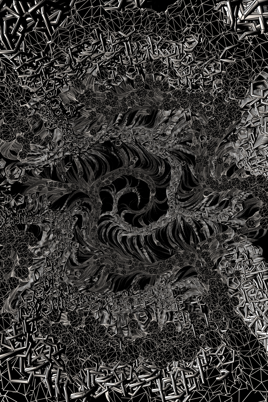
All geometric complexity of lattices, which are the main aesthetic elements behind O B S C V R V M, comes from this loop. This inconspicuous loop above is the core algorithm behind the entire collection. In it, lattice_mesh gets overwritten in every stage with a more and more complex lattice. The highest stage for a lattice in O B S C V R V M is 6, which means there are that many iteration steps. Stage 7 is possible to generate, but slows down even the most powerful computers. The highest stage we were able to generate was 11, but this was done in a fully different, non-real-time setup (also, not in a browser), where only a portion of the lattice was drawn. It's safe to say that there is a computational limit to how complex these lattices can become. In the above code, lattice_mesh_target is another lattice which can be used to create transition animation, but this feature was not implemented in this collection. Often we leave extra functionality in the codebase so we don't have to reinvent the wheel when we start working on another collection.
To actually draw the lattice geometry later, we are not using the Mesh object directly, instead we reformat it into a graph-like object gData. This was especially important for our previous collections Monocell, Chromoplasm and Crystalyx, where lattices were defined as particle-spring models with forces acting along edges connecting the nodes. gData contains lists for nodes as well as for links (edges between the nodes) where we can easily access the corresponding source and target nodes for each link. Every mesh geometry can be represented through a graph-like data structure, the only difference is which representation is more convenient for the task at hand. This conversion is very short and calls a mesh_to_gData() function from subdivision.js.
return mesh_to_gData(lattice_mesh, lattice_mesh_target, triangulate)
Geometry subdivision is a topic appearing in computer graphics and computational design and has a range of applications. If you want to get deeper into it, I held a tutorial for the students of Aalto University for the course Algorithmic Design titled Subdivision, which is available online. It uses Python, Rhino and Processing, but the algorithms are exactly the same. In fact, the code from the video was adapted to become the code you are reading about in this article.
This concludes lattice generation part. Now we have the gData object which defines the lattice geometry, but we still need to tell three.js to draw it.
three.js scene setup
Going back to main.js, after we have gDatas (list containing gData objects which define different lattices) the code proceeds with a more or less standard boilerplate part for three.js. This part is extensively covered in standard three.js documentation and tutorials, so we will not focus too much on it here. Still, we do want to list few important parts which affect our piece, and we will present them here briefly for context but without many parts in between.
First, we need to define our WebGL renderer:
var renderer = new THREE.WebGLRenderer({antialias: true, alpha: true, preserveDrawingBuffer: true});
renderer.shadowMap.enabled = true;
We turn on antialias for sharper lines, and set alpha and preserveDrawingBuffer to true. Also, the entire light vs shadow aesthetics of O B S C V R V M depends on shadow maps, so we need to turn these on as well.
NOTE ON THUMBNAILS: If you want to use canvas capture feature for thumbnails for your fxhash collection, preserveDrawingBuffer needs to be set to true, otherwise your capture will return blank thumbnails. The other option is to use viewport capture, but this is a suboptimal solution if your pieces have different aspect ratio for the canvas like ours. If you want thumbnails to have the same proportion as you piece canvas (and look good on fxhash website) you should use capture canvas option.
Additionally, for canvas capture to work on fxhash website, you need to give an id to your no-name, three.js standard canvas element:
renderer.domElement.id = 'obscvrvmcanvas'; // now you can use canvas css selector: canvas#obscvrvmcanvas on fxhash website
We determine the viewportWidth and viewportHeight based on the three different aspect ratios our pieces have (0.75, 1.0, 1.5):
var viewport = document.getElementById("viewport");
var margin_left = 0;
var margin_top = 0;

if (window.innerWidth / aspect_ratio > window.innerHeight) { //If target viewport height is larger then inner height
  viewportHeight = window.innerHeight; // force height to be inner Height
  viewportWidth = aspect_ratio * window.innerHeight;  // scale width proportionally
  margin_top = 0;
  margin_left = (window.innerWidth - viewportWidth) / 2;

} else {  // if target viewport width is larger then inner width
  viewportHeight = window.innerWidth / aspect_ratio; // scale viewport height proportionally
  viewportWidth = window.innerWidth; // force width to be inner Height
  margin_top = (window.innerHeight - viewportHeight) / 2;
  margin_left = 0;
}

viewport.style.marginTop = margin_top + 'px';
viewport.style.marginLeft = margin_left + 'px';
For the scene we decided to use an orthographic camera. We did many tests with the perspective view as well, but we found that depth layering of complex lattice geometry coupled with strong light and shadow contrast produces an overwhelming and unreadable scene. In parallel view, many lattice members align perfectly and produce a nicer pattern, while the "hidden" parts of the lattice still throw shadows on the whole composition. We define our orthographic camera in a standard way:
var cam_factor = 4; // controls the "zoom" when using orthographic camera
cam_factor_mod = cam_factor * Math.min(viewportWidth/1000, viewportHeight/1000);

var camera = new THREE.OrthographicCamera( -viewportWidth/cam_factor_mod, viewportWidth/cam_factor_mod, viewportHeight/cam_factor_mod, -viewportHeight/cam_factor_mod, 0, 5000 );

camera.position.set(0, 0, 2000);
camera.lookAt(new THREE.Vector3(0, 0, 0));
To light our scene, we define a single traveling point light. Ambient light is defined but after many tests, we found that the best intensity for it was zero! This gave us a strong, space-like light-shadow contrast.
// ADD LIGHTING
const color = 0xffffff; // white
const intensity = 0.0; //0-1, zero works great for shadows with strong contrast

var light = new THREE.PointLight(color);
light.position.set(0, 0, 2000);
light.castShadow = true;
scene.add(light);

const amblight = new THREE.AmbientLight(color, intensity);
scene.add(amblight);
Point light is traveling along a circular path around the origin of the whole scene. As it is a simple circle, we use a circle equation to get the coordinates for each light_angle. Parameter light_source_type (can take form of 'west', 'east', 'north' and 'south') defined in generate_composition_params() function determines the plane in which this circular path lays and the direction of travel. Like all animation in three.js, we update the point light position using JS setInterval() function.
// LIGHT TRAVEL PARAMETERS
var light_framerate = 50;
var base_light_angle = Math.PI/3; // starting angle, angle 0 is straight behind the camera
base_light_angle_step = 0.0005;
//var light_angle; // defined already before
var light_angle_step;

if (light_source_type == 'west') {
  light_angle = -base_light_angle;
  light_angle_step = base_light_angle_step;
} else if (light_source_type == 'east') {
  light_angle = base_light_angle;
  light_angle_step = -base_light_angle_step;
} else if (light_source_type == 'north') {
  light_angle = base_light_angle;
  light_angle_step = -base_light_angle_step;
} else if (light_source_type == 'south') {
  light_angle = -base_light_angle;
  light_angle_step = base_light_angle_step;
}

// LIGHT TRAVEL LOGIC
var arc_division = 1.0;
const lp = view.light.position;
function update_light_position () {
  light_angle += light_angle_step*arc_division;

  if ((light_source_type == 'west') || (light_source_type == 'east')) {
    // rotation in XY plane
    view.light.position.set(Math.sin(light_angle) * parallex_amplitude, lp.y, Math.cos(light_angle) * parallex_amplitude);
  } else if ((light_source_type == 'north') || (light_source_type == 'south')) {
    // rotation in YZ plane
    view.light.position.set(lp.x, Math.sin(light_angle) * parallex_amplitude, Math.cos(light_angle) * parallex_amplitude);
  }
  // rotation in XZ plane - not used but we keep the equation here for convenience
  //view.light.position.set(Math.sin(light_angle)*parallex_amplitude, Math.cos(light_angle)*parallex_amplitude, lp.z);
}

var lightIntervalInstance = setInterval(function () {update_light_position()}, light_framerate);
Few important things related to shadows. In computer graphics, shadows are computed using shadow maps on which the geometry is projected and which are in turn texturing the objects with shadow textures. The size of this shadow map texture determines how much GPU memory needs to be allocated to calculate the scene. Needless to say, as our lattices have hundreds or even thousands of geometry elements (cylinders) the size of this shadow maps will effect performance. Smaller shadow maps means better performance, but as the lattice is composed of thin members, we will have a lot of flickering throughout the scene. We set the default shadow parameter to 4096 pix (size of the shadow map in pixels), which seems to work ok on most devices we tested, except iOS! Unfortunately, iOS limits the maximum memory a browser app can access, so we had to resort to detecting if the device accessing the piece was running iOS, then manually setting shadow map size to 2048 pix, half of what is used on other devices. Luckily, pixel density is also higher on iOS devices so this degradation of shadow maps is less noticeable. We wanted to provide a way to modify this shadow map size in the future (maybe Apple fixes their iPhones to run 3D apps in browsers properly) so we implemented a query string for setting shadow map size. You can manually set a shadow map size by passing a query string to the URL of the form ?shadow=value, for example ?shadow=4096, ?shadow=2048 etc. In the code, this is implemented the following way:
var shadow = 2048; //Default
var paramsAssigned = false;
// URL PARAMS
// Usage: add this to the url ?shadow=4096
try {
  const queryString = window.location.search;
  const urlParams = new URLSearchParams(queryString);
  const shadowString = urlParams.get('shadow');

if (shadowString!=null) {
    shadow = Math.abs(parseInt(shadowString));
    paramsAssigned = true;
  }
} catch (error) {
  //console.log("shadow variable must be a positive integer")
}
if (Number.isInteger(shadow) & paramsAssigned) { //If values are overiden by urlParams  for a minimum overide add: & shadow > 2048
  console.log("Using custom url parmater for shadow map size: " + shadow.toString())
  light.shadow.mapSize.width = shadow;
  light.shadow.mapSize.height = shadow;
} else if (Number.isInteger(shadow) & iOS()) {
  //console.log("iOS")
  light.shadow.mapSize.width = Math.min(shadow, 2048); //increase for better quality of shadow, standard is 2048
  light.shadow.mapSize.height = Math.min(shadow, 2048);
} else if ((Number.isInteger(shadow) & !iOS())){
  //console.log("!iOS")
  light.shadow.mapSize.width = Math.max(shadow, 4096);
  light.shadow.mapSize.height = Math.max(shadow, 4096);
} else {
  //console.log("Using default shadow map.")
  light.shadow.mapSize.width = 4096;
  light.shadow.mapSize.height = 4096;
}
How do we know if the device displaying the piece is running iOS? We implemented a special iOS() function which returns true or false depending if the iOS was detected, you can find it in utils.js.
function iOS() {
  return [
    'iPad Simulator',
    'iPhone Simulator',
    'iPod Simulator',
    'iPad',
    'iPhone',
    'iPod'
  ].includes(navigator.platform)
  // iPad on iOS 13 detection
  || (navigator.userAgent.includes("Mac") && "ontouchend" in document)
}
So much for the three.js scene setup. There are few other important elements which we didn't cover, but we encourage you to explore them yourself in the code, namely canvas resizing when the browser window is resized with function onWindowResize(), image and gif capture with CCapture.js, and loading screen display with an animated gif using some html.
Drawing the lattice
To draw all elements of the scene, we run drawing functions which are prototypes of a View object which defines the scene, concluding with the render call.
// drawing everything in the scene
view.addInstances(); // draws all lattices based on data from gDatas
view.addStarsOrdered(); // draws ordered stars based on lattice nodes from nDatas
view.addStarsRandom(random_starfield_bounds, nr_of_random_stars); // draws random stars - parameters > (bounds, quantity)

// all celestial objects from the celestial_object_types list will be added here
if (celestial_object_types[0] != 'none') {
  for (var i = 0; i < celestial_object_types.length; i++) {
    view.addCelestialObject(celestial_object_types[i]); // draws celestial objects based on the input list
  }
}

view.render();
Function view.addInstances(); which draws all lattice geometries from gDatas object, is over 250 lines long. This is because we are using it not only to draw the lattice, but also to define explosion and debris from the explosion. In hindsight, we could have split it in multiple functions to make the code more readable. We will go step by step through it to really understand what is happening.
First, we would like to show you how the function would look like if we would only draw the lattice using instanced mesh geometry, without special cases and explosions. Instanced mesh geometry is the reason why O B S C V R V M can display such complex geometry in your browser, shadows and all, so it's worth explaining how it works. Here is how a simplified view.addInstances(); function looks like:
View.prototype.addInstances = function  () {
  // iterating through different lattices
  for (var n = 0; n < gDatas.length; n++) {
      var gData = gDatas[n];
      var dummy = new THREE.Object3D();
      var geometry = new THREE.CylinderGeometry(  cylinder_params[c_type][0],
                                                  cylinder_params[c_type][1],
                                                  cylinder_params[c_type][2],
                                                  cylinder_params[c_type][3],
                                                  cylinder_params[c_type][4],
                                                  true);

      var material = new THREE.MeshPhongMaterial({color: 0xffffff});
      var imesh = new THREE.InstancedMesh(geometry, material, gData.links.length)
      var axis = new THREE.Vector3(0, 1, 0);
      imesh.instanceMatrix.setUsage(THREE.DynamicDrawUsage); // will be updated every frame
      var c = new THREE.Color()

      // iterating through members of a single lattice
      for (var i = 0; i < gData.links.length; i++) {
        var source_index = gData.links[i]['source'];
        var target_index = gData.links[i]['target'];
        var vector = new THREE.Vector3(   gData.nodes[target_index].x-gData.nodes[source_index].x,
                                          gData.nodes[target_index].y-gData.nodes[source_index].y,
                                          gData.nodes[target_index].z-gData.nodes[source_index].z);

        dummy.scale.set(  c_xy_scale[gData.nodes[source_index]['stage']],
                          gData.links[i]['value'],
                          c_xy_scale[gData.nodes[source_index]['stage']]);

        dummy.quaternion.setFromUnitVectors(axis, vector.clone().normalize());
        dummy.position.set( (gData.nodes[source_index].x + gData.nodes[target_index].x) / 2,
                            (gData.nodes[source_index].y + gData.nodes[target_index].y) / 2,
                            (gData.nodes[source_index].z + gData.nodes[target_index].z) / 2)
        dummy.updateMatrix();
        imesh.setMatrixAt(i, dummy.matrix);
      }

      imesh.instanceMatrix.needsUpdate = true
      imesh.castShadow = true;
      imesh.receiveShadow = true;

      this.scene.add(imesh); // adding instanced mesh to the scene
  }
}
Instanced mesh is faster to display on your GPU because only the vertices of a single mesh object are stored, together with transformation matrices for each instance in the scene. This works if you have to display many mesh objects which are the same or similar (just rotated or scaled) as storing transformation matrices is much lighter than storing the information for the entire mesh. In our case, the basic mesh is a cylinder which we create with THREE.CylinderGeometry() function, but instead of using THREE.Mesh() function to create a mesh out of it, we use THREE.InstancedMesh(). Now we defined a basic mesh once, and we define a transformation matrix for each instance in the scene with imesh.setMatrixAt(); A small trick we use here is to create this matrix by creating a dummy object of the type THREE.Object3D(), then use the methods of that object to conveniently rotate its matrix to align with our lattice member. This is done using quaternions and setFromUnitVectors() method. We know the alignment of our lattice members by querying gData object, namely its links list to get source and target node indices. links list also stores 'value' property, which is the length of the member. By setting a y scale of the member to this number using dummy.scale.set(), the instanced cylinder will have the length of the corresponding link. x and z scales define the thickness of the member and are derived from a separate list which sets their value according to the stage at which the source node of that link was created. Remember, our custom Node object had a fourth entry for storing the stage number for every Node object, this is where we're using it now. We also define that members which are created at later stages should be thinner in diameter in the following way:
// in params.js
// how much is thickness of the member scaled for every stage
const thickness_scale_per_stage = {
  'getting_thinner' : [1.2, 1.1, 1.0, 0.9, 0.8, 0.7, 0.6, 0.6, 0.6]
};

// in main.js in View.prototype.addInstances()
var c_xy_scale = thickness_scale_per_stage['getting_thinner']; // how much is thickness of the member scaled for every stage

dummy.scale.set(  c_xy_scale[gData.nodes[source_index]['stage']],
                  gData.links[i]['value'],
                  c_xy_scale[gData.nodes[source_index]['stage']]);
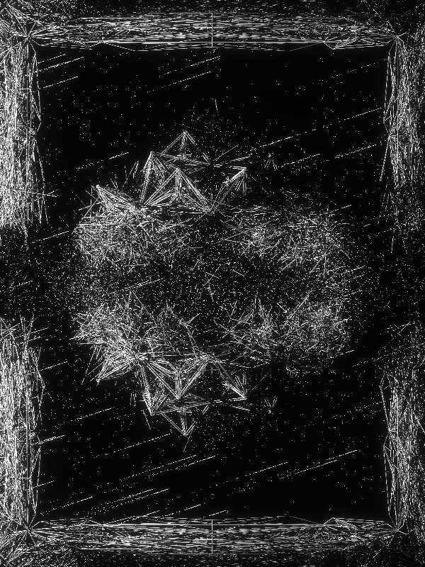
Explosions and entropy
This covers our approach on instanced meshes. Next, if we want to introduce entropy, chaos and explosions, we can do this simply by modifying the transformation matrix before we define it with imesh.setMatrixAt(); method. We will not look at all explosion types (there are six of them) but only at the last one (explosion_type == 6) which defines two explosion centers mirrored around the center to calculate the displacement (as a token feature it is labeled 'pierced' together with explosion_type == 5) This produces a pleasing symmetrical explosion. First, we need to define these explosion centers, which is done in params.js in generate_composition_params() function.
var explosion_center_a = new THREE.Vector3(gene_range(-200, 200), gene_range(-200, 200), 0); // random point in the middle of the scene
var explosion_center_b = new THREE.Vector3(-explosion_center_a.x, -explosion_center_a.y, 0); // same but mirrored around the center
At the top of the View.prototype.addInstances() function back in main.js, we define parameters of the explosion. We are using an approximate "discrete" approach to handle explosion effects, separating exploded members in distance bands and calculating effects for members in each band separately. These distances are defined in cull_dist_bands list, totaling four bands or distance areas. A more accurate approach would be to define a distance function and use it to calculate explosion effects. This would make the code shorter but also harder to handle and debug, especially as real life explosions have non-linear effects. By using this discrete approach, we have full control over the explosion effects in each band. We also define the percentage of members culled (removed) from the scene by the explosion, the random rotation of the remaining ones, absolute explosion strength (used for displacement) and spread of explosion debris.
// parameters for explosion from a point, we define different values if the explosion is along an axis
var cull_dist_bands = [40, 80, 120, 160]; // explosion will be moderated in these distance bands ("discrete" approach)
var cull_precentage_bands = [1.0, 0.8, 0.6, 0.4]; // in each explosion distance band we will randomly remove this % of members
var explosion_strength = 1000; // absolute scaling factor for the explosion effect
var explosion_rot_range = Math.PI/2; // exploded members will be randomly rotated within this angle range
var explosion_rot_reduction = [1.0, 0.6, 0.3]; // random rotation range will be reduced for each explosion distance band
var triangle_radius = 0.5; // triangles for the debris
var debris_multiplier = 5; // multiply the number of debris particles
var debris_spread = 50; // distance range to randomly spread out the debris particles
project name project name project name
To calculate explosion effects on each member of the lattice, we have to calculate the distance of that member to the explosion center. As it is enough to use an approximation here, we do this by calculating the distance to the center point of the member. We also keep track if any of the ends of the member come too close to the explosion center, in which case we can remove it at a later stage. This avoids certain weird situations where an area of the lattice is completely cleared by the blast but some long members would remain because their center points were too far. This is how we calculate all relevant distances:
// calculating distances from a member to explosion centers
var projected_member_cent =  new THREE.Vector3((gData.nodes[source_index].x + gData.nodes[target_index].x) / 2, (gData.nodes[source_index].y + gData.nodes[target_index].y) / 2, 0);
var projected_source = new THREE.Vector3(gData.nodes[source_index].x, gData.nodes[source_index].y, 0);
var projected_target = new THREE.Vector3(gData.nodes[target_index].x, gData.nodes[target_index].y, 0);
var dist_to_cent_a = projected_member_cent.distanceTo(explosion_center_a);
var dist_to_cent_b = projected_member_cent.distanceTo(explosion_center_b);
var dist_end_to_cent_a = Math.min(dist_source_to_cent_a, dist_target_to_cent_a);
var dist_source_to_cent_b = projected_source.distanceTo(explosion_center_b);
var dist_target_to_cent_b = projected_target.distanceTo(explosion_center_b);
var dist_end_to_cent_b = Math.min(dist_source_to_cent_b, dist_target_to_cent_b);

// calculating explosion axis
var explosion_axis = new THREE.Vector3((gData.nodes[source_index].x + gData.nodes[target_index].x) / 2, (gData.nodes[source_index].y + gData.nodes[target_index].y) / 2, (gData.nodes[source_index].z + gData.nodes[target_index].z) / 2).normalize();

// in the code this is in fact else if statement, but we write it here like this for simplicity
if (explosion_type == 6) {
  dist_to_axis = Math.min(dist_to_cent_a, dist_to_cent_b);
  dist_to_axis_explosion = Math.min(dist_to_cent_a, dist_to_cent_b);
  end_to_axis = Math.min(dist_end_to_cent_a, dist_end_to_cent_b);
}
We mentioned that we handle explosion effects in bands defined by cull_dist_bands list. We can check if the member falls inside an explosion distance band by calculating the Boolean value for (end_to_axis < cull_dist_bands[n]) || (dist_to_axis < cull_dist_bands[n]) where n is the index for the band we want to check (0-3 in our case). We handle each band separately through a conditional statement. Let's look at how the code for the last distance band looks like, the others are almost the same with some slight modification of parameters:
// in the code this is in fact else if statement, but we write it here like this for simplicity
if ((end_to_axis < cull_dist_bands[3]) || (dist_to_axis < cull_dist_bands[3])) {
  // apply explosion offset and random rotation for member within the explosion zone
  dummy.translateOnAxis(explosion_axis, explosion_strength / dist_to_axis_explosion);
  dummy.rotateX(explosion_rot_reduction[2] * (gene() * explosion_rot_range * 2 - explosion_rot_range));
  dummy.rotateY(explosion_rot_reduction[2] * (gene() * explosion_rot_range * 2 - explosion_rot_range));
  dummy.rotateZ(explosion_rot_reduction[2] * (gene() * explosion_rot_range * 2 - explosion_rot_range));
  dummy.updateMatrix();
  // third band, 40% of members get culled
  if (gene() < cull_precentage_bands[3]) {
    cull_member = true;
    debris_position_temp = new THREE.Vector3((gData.nodes[source_index].x+gData.nodes[target_index].x)/2, (gData.nodes[source_index].y+gData.nodes[target_index].y)/2, (gData.nodes[source_index].z+gData.nodes[target_index].z)/2);
    // debris will be pushed away from the axis the same as the members
    debris_position_temp.add(explosion_axis.multiplyScalar(explosion_strength / dist_to_axis_explosion));
    for (var d = 0; d < debris_multiplier; d++) {exploded_dummies.push(debris_position_temp);}
  }
}
To apply position displacement for the member we modify its transformation matrix using translateOnAxis(), and apply random rotation with rotateX(), rotateY() and rotateZ() methods. explosion_axis, vector connecting the center point of the member and the explosion center, is the direction of displacement. The amount of displacement is proportional to the explosion_strength parameter and reverse proportional to the distance to the center of explosion. This is in fact how real explosions work, although the energy of explosion is reverse proportional to the square of the distance (again, we're using an approximation here). We also decide if the member is culled (left out) by setting cull_member to either true or false using probabilities from cull_precentage_bands list. Lastly, to define positions of debris triangles later, we store positions of all exploded members inside debris_position_temp, calculate their exploded position (by adding their position to the scaled explosion_axis through add() method) and then store that translated transformation matrix inside exploded_dummies list. Remember, we can use vector math here to speed up the calculation and simplify the syntax, for example when we are adding points and vectors together (this is equivalent to translation). Notice that we store multiple copies of dummy objects, number of which depends on debris_multiplier, and pack it using a short loop. This means we will have more than one debris element (triangle) for each exploded member. To actually skip drawing the lattice member if it's exploded, we need to set a condition and skip adding its transformation matrix to the instanced mesh:
// cull_member is set per default to false, unless explosion part above defined it to be true
if (!cull_member) {
  imesh.setMatrixAt( i, dummy.matrix );
}
Exploded things leave debris, right? We can use previously stored transformation matrices of exploded members from exploded_dummies list to position small triangles around the area of explosion which will look like explosion debris.
// EXPLOSION DUST CLOUD

// one triangle
const vertices = [
  0, 1, 0, // top
  1, 0, 0, // right
  -1, 0, 0 // left
];
const faces = [ 2, 1, 0 ]; // only one face

var dummy = new THREE.Object3D();
var triangle = new THREE.PolyhedronGeometry(vertices, faces, triangle_radius, 0);
triangle.scale(0.5, 10, 0.5);
var imesh_debris = new THREE.InstancedMesh( triangle, material, exploded_dummies.length )
imesh_debris.instanceMatrix.setUsage(THREE.DynamicDrawUsage); // will be updated every frame

for (var i = 0; i < exploded_dummies.length; i++) {
  dummy.position.set(exploded_dummies[i].x, exploded_dummies[i].y, exploded_dummies[i].z);
  var random_axis = new THREE.Vector3(gene() * 2 - 1, gene() * 2 - 1, gene() * 2 - 1).normalize();
  dummy.translateOnAxis(random_axis, gene() * debris_spread);
  var uniscale = 0.2 + gene();
  dummy.scale.set(uniscale, uniscale, uniscale);
  dummy.rotateX(gene() * Math.PI/3 - Math.PI/6);
  dummy.rotateY(gene() * Math.PI/3 - Math.PI/6);
  dummy.rotateZ(gene() * Math.PI/3 - Math.PI/6);
  dummy.updateMatrix();
  imesh_debris.setMatrixAt(i, dummy.matrix);
}

imesh_debris.instanceMatrix.needsUpdate = true
//imesh_debris.castShadow = true; // remove for performance
imesh_debris.receiveShadow = true;
this.scene.add(imesh_debris);
You might notice this part of the code looks very much like the one where we draw lattice members using instanced mesh. This is because it is, except instead of cylinders, we use triangles to draw the instanced mesh. This basic triangle is defined above from scratch, it could also be used to define any other polygon (although in the end we opted for the simplest polygon there is - triangle). Triangle is also elongated so it looks more like a shattered piece of glass. We again use a dummy object of the type THREE.Object3D() as a convenient way to handle transformation matrices, and assign random displacement with translateOnAxis(), random rotations with rotateX(), rotateY() and rotateZ(), and random scale with scale.set() methods. To improve performance, we disabled shadow casting for the debris triangles. They still receive shadows, they are just not projecting any to surrounding geometry. This concludes drawing of the lattices and explosions. The only elements left to draw are the stars and celestial objects.
Drawing stars
We already mentioned the functions that draw our scene. To recap, here are the two functions that draw the star field:
view.addStarsOrdered(); // draws ordered stars based on lattice nodes from nDatas
view.addStarsRandom(random_starfield_bounds, nr_of_random_stars); // draws random stars - parameters > (bounds, quantity)
These two functions are very similar, and in the beginning they were part of the same function. We decided to split them to aid readability, although you could for sure join them together. Remember, every time you're repeating part of the code, you could consider writing a function that replaces that part and use a function call instead of writing that block of code. But, life is not ideal, and we are not perfect programmers, and we have limited time to "refactor" the code, so sometimes we leave the code in it's longer, inefficient form if it does what we want. A radical way of applying this would be the moto: if it works, don't fix (change) it! So let's have a look at the function that draws the ordered star field.
// takes as an input nData object for location of stars
View.prototype.addStarsOrdered = function ()
{
  var star_plane_distance = -2000; // z coordinate of the plane where stars reside (they also recieve no shadow)
  var star_jitter = 10; // every lattice node is randomly jittered so the stars don't align
  // one triangle
  const vertices = [
    0, 1, 0, // top
    1, 0, 0, // right
    -1, 0, 0 // left
  ];
  // only one face
  const faces = [ 2, 1, 0 ];
  const triangle_radius = 0.30;

  const geometry = new THREE.PolyhedronGeometry(vertices, faces, triangle_radius, 0);
  geometry.scale(1, 1.5, 1);
  const material = new THREE.MeshPhongMaterial({color: 0xffffff});

  for (var n = 0; n < nDatas.length; n++) {
    var nData = nDatas[n];
    const imesh = new THREE.InstancedMesh( geometry, material, nData.nodes.length )
    imesh.instanceMatrix.setUsage(THREE.DynamicDrawUsage); // will be updated every frame

    for (var i = 0; i < nData.nodes.length; i++) {
      const dummy = new THREE.Object3D();
      var uniscale = 0.5 + gene();
      dummy.scale.set(uniscale,uniscale,uniscale);
      dummy.position.set( nData.nodes[i].x + gene_range(-star_jitter, star_jitter),
                          nData.nodes[i].y + gene_range(-star_jitter, star_jitter),
                          star_plane_distance);
      dummy.rotateX(gene() * Math.PI/3 - Math.PI/6);
      dummy.rotateY(gene() * Math.PI/3 - Math.PI/6);
      dummy.rotateZ(gene() * Math.PI/3 - Math.PI/6);
      dummy.updateMatrix();
      imesh.setMatrixAt( i, dummy.matrix );
  }

  imesh.instanceMatrix.needsUpdate = true;
  //imesh.castShadow = true; // remove for performance
  //imesh.receiveShadow = true; // stars recieve no shadow
  this.scene.add(imesh);
  }
}
project name project name project name
Again, this part of the code is very similar to how we draw the lattice and explosion debris, because it too uses instanced mesh to draw the stars, which are small triangles (just like the explosion debris). The only real difference is how the position of these stars (triangles) is defined. Also, the stars don't receive nor cast shadows. At the very top of main.js, we defined nDatas list, which holds nData objects (in our case, only one is created and pushed into the list):
var nDatas = [];
var nData;

// LATTICE 3 - STARS, ordered, triangles
// all input parameters are optional, they will be chosen at random if not passed into the function
lattice_params = generate_lattice_params('plane', 6);
nData = generate_lattice(lattice_params);
nDatas.push(nData);
What exactly is nData and how is it different from gData? It is in fact the very same object, with the same internal structure. So, to draw the ordered star field, we apply the same algorithm for generating lattice parameters. The ordered stars are created with the same algorithm as the lattices. We just give that object a different name to designate we will use it for the stars, not for the lattice. Also, we fix the primitive type and the number of stages, so there is less variety as with the lattices. In the view.addStarsOrdered(); function we define the positions of stars like this:
// position for ordered stars comes from nData object
dummy.position.set( nData.nodes[i].x + gene_range(-star_jitter, star_jitter),
                    nData.nodes[i].y + gene_range(-star_jitter, star_jitter),
                    star_plane_distance);
The position of stars is just the position of the nodes of the corresponding lattice, plus a random offset with star_jitter as the range. gene_range() is a random function which returns a random number between a defined range with uniform distribution. All stars have the same z coordinate star_plane_distance, which essentially projects all the nodes to that XY plane. We mentioned that the whole scene resembles theater scenography, so although stars could be distributed in space, they are "flattened" to this star plane at the very back of the scene.
This covers the ordered stars. There are also random stars that are overlaid on top which we draw with view.addStarsRandom() function.
// STARS - random
var random_starfield_bounds = 1500;
var nr_of_random_stars = 10000;

view.addStarsRandom(random_starfield_bounds, nr_of_random_stars); // draws random stars - parameters > (bounds, quantity)
As already mentioned, this function is the same as for the ordered stars, except instead of using lattice parameters from nDatas list, we just use the random positions sampled within a bounding square, with nr_of_random_stars controlling the number of times the loop runs.
// position for random stars is just a random position sampled from a bounding square
dummy.position.set(gene() * bounds - bounds/2, gene() * bounds - bounds/2, star_plane_distance);
The overlay of these random stars, coupled with the random jitter of the ordered ones, produces a natural, yet eerily ordered star field, just what we need for that space gothic feeling.
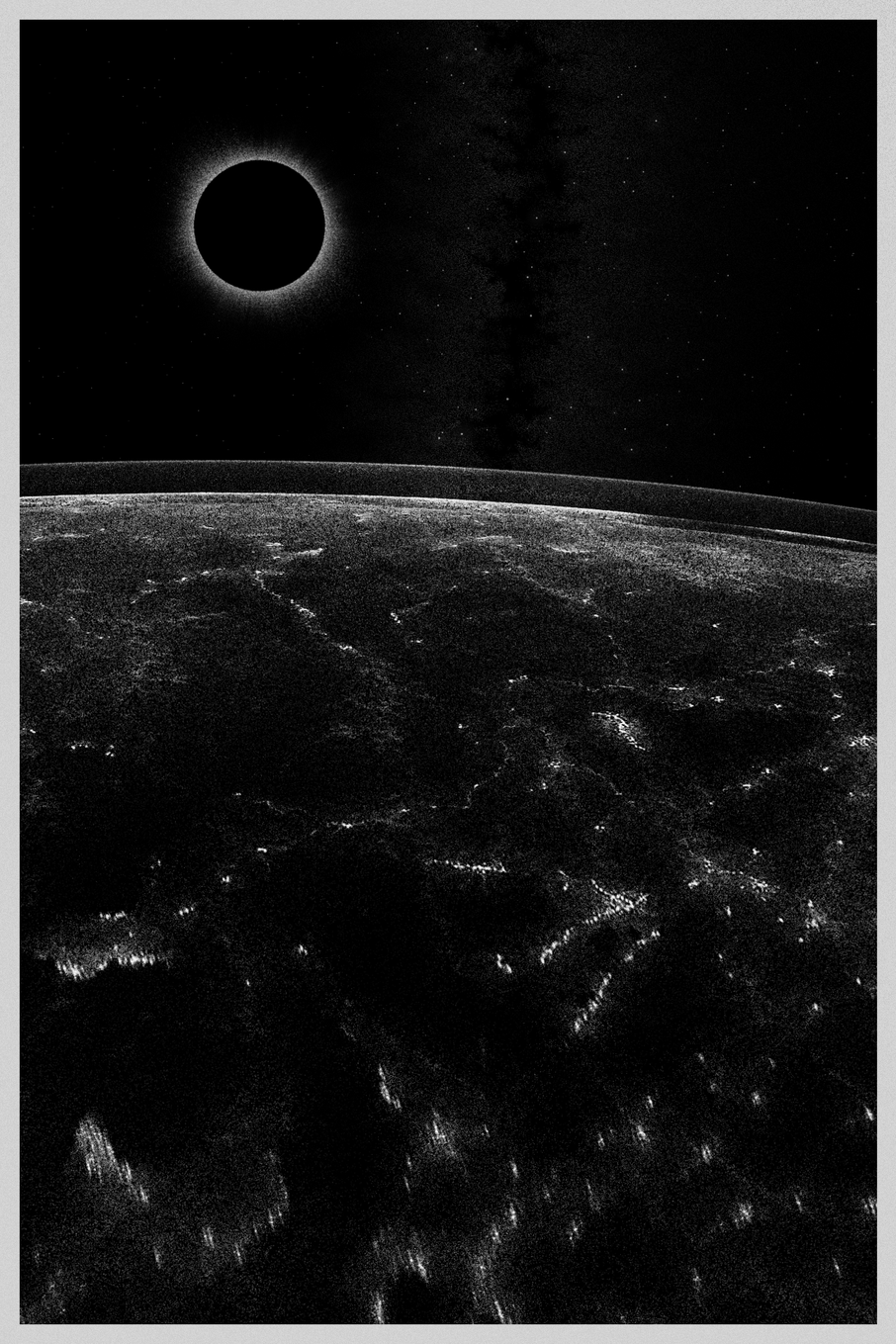
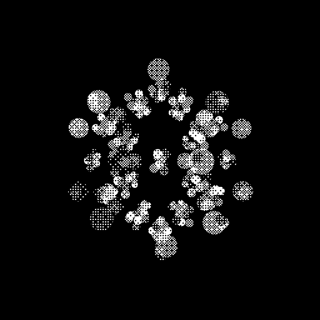
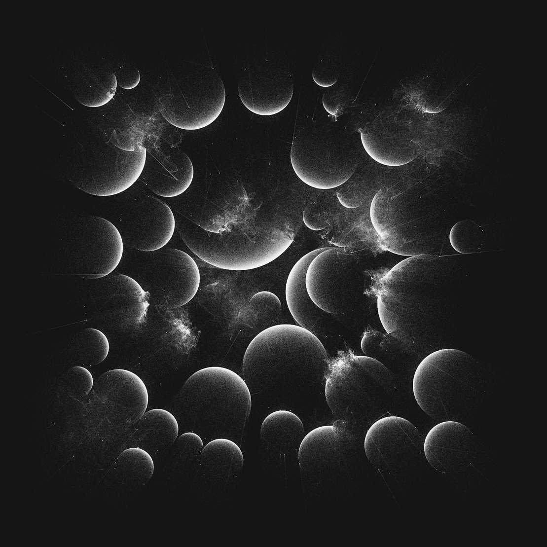
Drawing celestial bodies
Celestials are objects which appear in most of the O B S C V R V M pieces in the background. At times, it seemed as if they deserve a whole collection devoted to them, and certainly this would justify the time we spent on their development. We were inspired to put them in after seeing great collections like ’s “adrift” and 's “Heat Death”, which both feature code generated celestial objects. In O B S C V R V M, celestial objects that appear are:
- comet
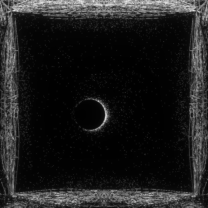
- eclipse
- ultra eclipse
- moon
- planet
- orbit
- meteor shower
- quasar
- nova
- rapture - misspelling of rupture (yes we make mistakes)
- constellation
Their probabilities and combinations vary depending on the state (pristine, sliced or pierced) and center piece type. These are defined in params.js through allele objects, for example the allel_celestial_object_types_empty:
const allel_celestial_object_types_empty = [
  [['none'], 10],
  [['comet'], 5], [['comet', 'eclipse'], 2], [['comet', 'moon'], 2], [['comet', 'planet'], 2], [['comet', 'orbit'], 2], [['comet', 'meteor shower'], 2],
  [['eclipse'], 10],
  [['ultra eclipse'], 3],
  [['moon'], 15],
  [['planet'], 5],
  [['orbit'], 5],
  [['meteor shower'], 10], [['meteor shower', 'eclipse'], 2], [['meteor shower', 'moon'], 2], [['meteor shower', 'planet'], 2], [['meteor shower', 'orbit'], 1],
  [['quasar'], 5],
  [['nova'], 5],
  [['rapture'], 5],
  [['constellation'], 5]
];
project name project name project name
This allele is used in generate_composition_params() when center_piece_type equals to 'none':
// first choice priority for celestial object types
if (center_piece_type == 'none') {celestial_object_types = gene_weighted_choice(allel_celestial_object_types_empty);}
celestial_object_types is a list that can contain multiple celestial objects, all of which are drawn by looping through and unpacking them one by one before being passed to view.addCelestialObject() function:
// all celestial objects from the celestial_object_types list will be added here
if (celestial_object_types[0] != 'none') {
  for (var i = 0; i < celestial_object_types.length; i++) {
    view.addCelestialObject(celestial_object_types[i]);
  }
}
In view.addCelestialObject() function we applied what we mentioned a little earlier, namely that sometimes you want to pack as much functionality into a single function. Well, this single function is able to draw all 11 celestial objects. It does this by spliting the whole function into a big conditional statement, where each part of the code can then be selected by evaluating celestial_object_type parameter. We cannot go through every celestial object as the function contains 487 lines of code (this would warrant a separate fx(text) article), so we will only look at one type. Let's see how a code would look like if we would only want the function to draw an eclipse, so celestial_object_type == 'eclipse'.
NOTE: this is basically cutting away 80% of the function, but it will help us see which parts are essential and which are just repetition. To only draw an eclipse, the function would look like this:
View.prototype.addCelestialObject = function (celestial_object_type)
{
  // general parameters
  var radius_x, radius_y, cent_x, cent_y, tilt_angle, nr_of_triangles, stdev, customGaussian, angle, r, celestial_x, celestial_y;
  var celestial_plane_distance = -1800; // z coordinate of the plane where stars reside (they also recieve no shadow)
  var monteCarloHit = true; // this will draw the triangle and is true by default, except for nebula case where it can become false
  var nr_of_tries = 100; // number of tries to try to displace the center of the celestial (used in a for loop)
  var cent_offset = center_piece_type != 'none' ? 100 : 0; // center offset is set if there is a lattice in the center, otherwise it's zero

  // parameters specific for drawing the eclipse
  radius_x = gene_range(10, 75);
  radius_y = radius_x;
  // here we are trying to choose the center until at least one coordinate is not close to the center (so it doesn't overlap with the lattice in the center)
  for (var i = 0; i < nr_of_tries; i++) {
    cent_x = gene_range(-100 - cent_offset/2, 100 + cent_offset/2);
    cent_y = gene_range(-100 - cent_offset/2, 100 + cent_offset/2);
    if (Math.max(Math.abs(cent_x), Math.abs(cent_y)) > cent_offset) {break;}
  }
  tilt_angle = gene_range(-Math.PI, Math.PI); // full 360 degrees
  nr_of_triangles = Math.ceil(1000 * Math.sqrt(radius_x));
  stdev = gene() < 0.25 ? 2.0 : 0.4;
  customGaussian = gaussian(0, stdev);

  // place dark disk behind the celestial objects but in front of the stars so they are covered
  if (celestial_object_type == 'eclipse' || celestial_object_type == 'ultra eclipse' || celestial_object_type == 'moon' || celestial_object_type == 'planet' || celestial_object_type == 'orbit' || celestial_object_type == 'rapture') {
    const dark_disc_geo = new THREE.CircleGeometry(radius_x, 16);
    const dark_disc_material = new THREE.MeshBasicMaterial({color: 0x000000});
    const dark_disc_mesh = new THREE.Mesh(dark_disc_geo, dark_disc_material);
    dark_disc_mesh.position.set(cent_x, cent_y, celestial_plane_distance - 100);
    this.scene.add(dark_disc_mesh);
  }

  // one triangle
  const vertices = [
    0, 1, 0, // top
    1, 0, 0, // right
    -1, 0, 0 // left
  ];
  // only one face
  const faces = [ 2, 1, 0 ];
  const triangle_radius = 0.30; //0.5

  const geometry = new THREE.PolyhedronGeometry(vertices, faces, triangle_radius, 0);
  geometry.scale(1, 1.5, 1);
  const material = new THREE.MeshPhongMaterial({color: 0xffffff});

  const imesh = new THREE.InstancedMesh( geometry, material, nr_of_triangles )
  imesh.instanceMatrix.setUsage(THREE.DynamicDrawUsage); // will be updated every frame

  // main loop that calcupates positions of all triangles
  for (var i = 0; i < nr_of_triangles; i++) {
    // puts a bias on one side of the circle - angle is determined by the tilt_angle - ECLIPSE
    angle = gene_range(-Math.PI * customGaussian(), Math.PI * customGaussian());
    // solar eclipse - ECLIPSE
    r = 1 / (1 - gene_range(0, gene_range(0, gene_range(0, gene_range(0, 1)))));

    // general parametrization for a tilted ellipse
    //https://math.stackexchange.com/questions/2645689/what-is-the-parametric-equation-of-a-rotated-ellipse-given-the-angle-of-rotatio
    celestial_x = cent_x + r * radius_x * Math.cos(angle) * Math.cos(tilt_angle) - r * radius_y * Math.sin(angle) * Math.sin(tilt_angle);
    celestial_y = cent_y + r * radius_x * Math.cos(angle) * Math.sin(tilt_angle) + r * radius_y * Math.sin(angle) * Math.cos(tilt_angle);

    const dummy = new THREE.Object3D();
    var uniscale = 0.5 + gene();
    dummy.scale.set(uniscale, uniscale, uniscale);
    dummy.position.set(celestial_x, celestial_y, celestial_plane_distance);
    dummy.rotateX(gene() * Math.PI/3 - Math.PI/6);
    dummy.rotateY(gene() * Math.PI/3 - Math.PI/6);
    dummy.rotateZ(gene() * Math.PI/3 - Math.PI/6);
    dummy.updateMatrix();
    // if any triangle ends up too far from the center, we don't draw it
    // also monteCarloHit == false can appear in nebula type
    if (Math.max(Math.abs(celestial_x), Math.abs(celestial_y)) < 1000 && monteCarloHit) {
      imesh.setMatrixAt( i, dummy.matrix );
    }
  }

  imesh.instanceMatrix.needsUpdate = true
  //imesh.castShadow = true; // remove for performance
  //imesh.receiveShadow = true; // stars recieve no shadow
  this.scene.add(imesh);
}
This is still a long function, so we will break it down even further. We start with defining variables used in the function and some general parameters. These are commented so you can see what they do:
// general parameters
var radius_x, radius_y, cent_x, cent_y, tilt_angle, nr_of_triangles, stdev, customGaussian, angle, r, celestial_x, celestial_y;
var celestial_plane_distance = -1800; // z coordinate of the plane where stars reside (they also recieve no shadow)
var monteCarloHit = true; // this will draw the triangle and is true by default, except for nebula case where it can become false
var nr_of_tries = 100; // number of tries to try to displace the center of the celestial (used in a for loop)
var cent_offset = center_piece_type != 'none' ? 100 : 0; // center offset is set if there is a lattice in the center, otherwise it's zero
Next, we proceed with parameters that are specific for drawing the eclipse. In the original code, this code would be defined for each celestial separately and selected by checking the value of celestial_object_type In our case, this would be celestial_object_type == 'eclipse' but we don't need to include it here:
// parameters specific for drawing the eclipse
radius_x = gene_range(10, 75);
radius_y = radius_x;
// here we are trying to choose the center until at least one coordinate is not close to the center (so it doesn't overlap with the lattice in the center)
for (var i = 0; i < nr_of_tries; i++) {
  cent_x = gene_range(-100 - cent_offset/2, 100 + cent_offset/2);
  cent_y = gene_range(-100 - cent_offset/2, 100 + cent_offset/2);
  if (Math.max(Math.abs(cent_x), Math.abs(cent_y)) > cent_offset) {break;}
}
tilt_angle = gene_range(-Math.PI, Math.PI); // full 360 degrees
nr_of_triangles = Math.ceil(1000 * Math.sqrt(radius_x));
stdev = gene() < 0.25 ? 2.0 : 0.4;
customGaussian = gaussian(0, stdev);
These are very standard parameters if you want to draw an ellipse. To determine the center point with cent_x and cent_y we are using a bit convoluted way to avoid placing the celestial in the middle area of the scene. This is where the center piece lattice will appear so we don't want the celestial to be covered by it. tilt_angle determines the rotation of the ellipse, but in our case, it will correspond to the asymmetric direction of the light appearing behind the dark object to form a eclipse. We are also using a custom Gaussian function called customGaussian, defined in utils.js, with standard deviation (stdev parameter) determining if there is asymmetry in the light or not. This function gives an approximation of a Gaussian distribution, which is good enough for us. These functions are very useful when we want to model anything that is asymmetrical but can be derived from an ellipse, like a comet, a meteor, light coming behind a planet etc. We also use it to draw diffuse rings around planets, novas and quasars. You can find a good discussion on Gaussian distributions and their implementations in JS in this Stack Overflow thread.
Next, when we draw an eclipse in our scene, it will be composed of small white triangles and otherwise fully transparent inbetween. To make the dark area of the planet cover the stars behind, we place a dark circular disk in between as well. We do this for all celestials which need to cover the background with a black area (some don't, like a comet, meteor shower, quasar and nova) using this piece of code:
// place dark disk behind the celestial objects but in front of the stars so they are covered
if (celestial_object_type == 'eclipse' || celestial_object_type == 'ultra eclipse' || celestial_object_type == 'moon' || celestial_object_type == 'planet' || celestial_object_type == 'orbit' || celestial_object_type == 'rapture') {
  const dark_disc_geo = new THREE.CircleGeometry(radius_x, 16);
  const dark_disc_material = new THREE.MeshBasicMaterial({color: 0x000000});
  const dark_disc_mesh = new THREE.Mesh(dark_disc_geo, dark_disc_material);
  dark_disc_mesh.position.set(cent_x, cent_y, celestial_plane_distance - 100);
  this.scene.add(dark_disc_mesh);
}
Then, we define our triangle mesh which will be used as instantiated mesh and copied thousands of times to draw an eclipse object. This is the same code we already used for the explosion debris and the stars, so we will not show it again. The really interesting part is happening when we enter the loop to draw every triangle nr_of_triangles times.
// puts a bias on one side of the circle - angle is determined by the tilt_angle - ECLIPSE
angle = gene_range(-Math.PI * customGaussian(), Math.PI * customGaussian());
// solar eclipse - ECLIPSE
r = 1 / (1 - gene_range(0, gene_range(0, gene_range(0, gene_range(0, 1)))));
Parameters angle and r will be different for each celestial and chosen using the above mentioned celestial_object_type == 'eclipse' syntax in a conditional statement (not shown here). To draw any circular object, we can either iterate through all angles with a certain step size, or choose an angle within a range randomly, which is what we are doing here. This will produce a less regular, more "drawn" look. If we want this angle to be sampled uniformly, we can use a standard Math.random() function or in our case, gene_range() function, with fixed ranges. But as we want to sometimes produce an asymmetrical result (light coming from behind the planet and lighting one side more than the other) we can modify this range with a customGaussian() function we defined earlier. Is the result symmetrical or not will depend on the chosen standard deviation (large standard deviation means more symmetrical result, in our case it was set to 2.0). But to get that special distribution of points in relation to their distance to the radius to produce an eclipse effect, we need to define the r parameter which scales the radius of our ellipse. We get r by essentially choosing a random number within a range 0-1, then choose another number between that one and zero, then repeat that process four times. Each time our random number is getting closer and closer to zero, which is pushing the point closer and closer to the center of the ellipse. When we subtract this number from 1, we get points which are closer and closer to the edge of the ellipse. This is now planets are shaded. Finally, we take reciprocal of that remainder to mirror the points to the other side of the ellipse edge to get the eclipse effect. Much of the magic of drawing celestial bodies in O B S C V R V M involves playing with this r parameter.
After we choose a random angle and the radius scaling factor r, we can use an equation for a tilted ellipse to get the coordinates for our point:
// general parametrization for a tilted ellipse
//https://math.stackexchange.com/questions/2645689/what-is-the-parametric-equation-of-a-rotated-ellipse-given-the-angle-of-rotatio
celestial_x = cent_x + r * radius_x * Math.cos(angle) * Math.cos(tilt_angle) - r * radius_y * Math.sin(angle) * Math.sin(tilt_angle);
celestial_y = cent_y + r * radius_x * Math.cos(angle) * Math.sin(tilt_angle) + r * radius_y * Math.sin(angle) * Math.cos(tilt_angle);
The rest of the function is the same as for drawing instantiated triangles for stars or explosion debris, we just have to make sure to set the location of the dummy object correctly with the coordinates we just calculated:
dummy.position.set(celestial_x, celestial_y, celestial_plane_distance);
We encourage you to look at how all the other celestials are created yourself. You might be surprised that they all use the exact same template, with most important parameters being the choice of the random angle and radius scaling factor r. Most combinations we "rediscovered" ourselves through trial and error, greatly inspired by generative artists like Yazid, TAKAWO Shunsuke and x0y0z0.
Conclusion
We were greatly inspired by ’s “adrift”, 's “Heat Death”, ’s “Cradle”, and 's and 's "Antiflow" collections on fxhash, both by their approach to code as well as aesthetic synthesis of elements of their work. They motivated us to leave our code open (unminified and unobfuscated), available on public repositories, and well documented through writing and talks so they can serve as inspiration to others. We believe that by sharing our code openly, we are raising the standard of all generative art on the platform and benefiting the entire Tezos NFT ecosystem (and beyond). Thus, we see our support for open generative tools as a mission every generative artist should partake in.
O B S C V R V M is created by in 2022.
Code by and .
Article written by .