How StrangerintheQ used rayhatching to create a castle
written by clauswilke
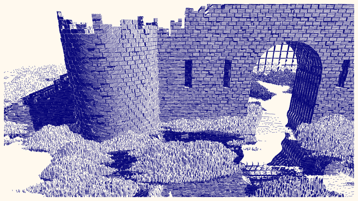
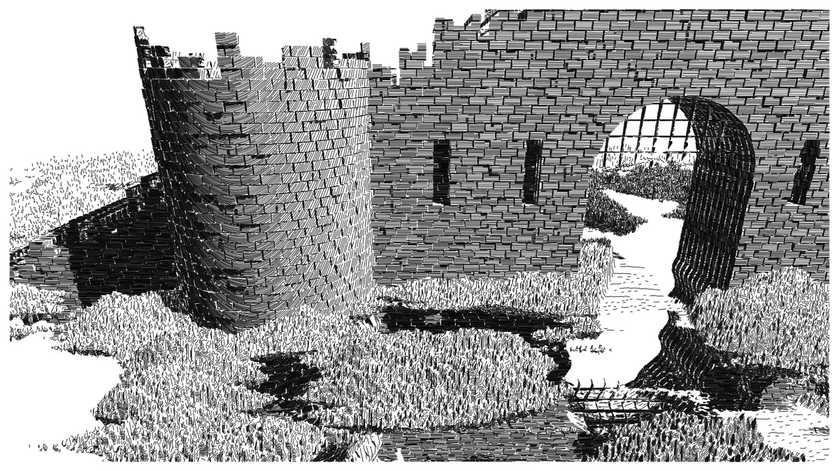
Output #317 of the Universal Rayhatcher project, "castle" by StrangerintheQ, is in my opinion one of the most impressive outputs in the entire collection. It just looks so real and melancholic. I wanted to understand how Stranger made it, and so I analyzed its signed distance function (SDF) character by character. Here I invite you into my journey into this piece. I will explain to you exactly how it works.
project name project name project name
But first, a couple of disclaimers. Most importantly, even though I explain every step along the way, this is a somewhat advanced article. If you have never studied SDFs before and/or if you're not familiar with the specific SDF language used by the Universal Rayhatcher project, you'll have to read some introductory articles first. Check out the various fxtext articles linked to the project and you'll find various introductory and intermediate articles written by a few different people. In particular, I strongly recommend you read "Getting Started with Universal Rayhatcher" by Ethspresso. Next, I do not hold the copyright to any of the SDF code I'm discussing here. I am reproducing this code here under fair use, simply to comment on it and to describe how it works. Please try to understand and apply the concepts, but do not copy the code verbatim into your own projects.
To reproduce the scene, we need to set the appropriate parameters in the rayhatcher development environment. First, we need to set the wallet to tz2MHcnM7fEVtExELMPBZb5njDweqMGvbn8A. I have done this at this link. Next, we need to set the appropriate parameters. Set a0 to 0.82, the title to "castle", background to "none", cam distance multiplier to 5, cam zoom to 1, max march distance to 200, mist start to 177, fudge factor to 0.26, and line width to 0.25.
The castle scene has four components: the wall, the tower, the ground, and the portcullis. (Check out this wikipedia article if you've never heard of a portcullis.) I'll discuss them in turn. Let's start with the wall.
The wall
First a few introductory remarks. We'll be using a rotated coordinate system, and in this coordinate system x runs back to front and z runs right to left. This is a bit unusual, as normally x would run left to right, and z back to front, so keep this in mind throughout. Larger x values means objects are further in the background, and larger z values means objects are further to the left.
We start with a very basic version of a wall, consisting of repeated cubes all along the z–y plane.
[x,z]=r0(x-20,z),
bx3(x,mod(y,1)-.5,mod(z,1)-.5,.45)
Each brick is of size 0.9 ✕ 0.9 ✕ 0.9 while occupying a unit cell, so it doesn't completely fill the available space. As a consequence we see distinct gaps between all the bricks.
To make the bricks more realistic, we have to make them wider than they are tall, and we also have to shift their positions in each row to create the impression of real masonry. We can make the bricks wider by simply dividing z by 2 (thus stretching space in the z direction). We shift them by counting rows and shifting the center point of each brick by one-third per row. The row count is simply r=Z(y), i.e. the integer part of y, since rows are one unit tall, and so we add r/3 to z inside the modulo function.
[x,z]=r0(x-20,z),
r=Z(y),
bx3(x,mod(y,1)-.5,mod(r/3+z/2,1)-.5,.45)
This is starting to look good, but it looks too regular. We can give the wall a more weathered appearance by pulling parts of the bricks in and out. We do so by adding ri(1,y,z)/3 to x inside the bx3() function.
[x,z]=r0(x-20,z),
r=Z(y),
bx3(x+ri(1,y,z)/3,mod(y,1)-.5,mod(r/3+z/2,1)-.5,.45)
Note that ri(1,y,z) changes only when the integral part of y or z changes, so we mostly get a distinct random shift for each brick. However, because bricks are shifted and stretched in the z direction, this doesn't quite work, and some bricks have two different shifts. This becomes visible when we zoom in and look from a slightly different angle. To try this out, set a0 to 0.9, cam dist multiplier to 0.6, and cam zoom to 4.
We could fix the code to not have this feature, by shifting the z coordinate appropriately inside the ri() function.
[x,z]=r0(x-20,z),
r=Z(y),
bx3(x+ri(1,y,r/3+z/2)/3,mod(y,1)-.5,mod(r/3+z/2,1)-.5,.45)
Stranger does not use this fix, however. We don't particularly notice the difference in the final image unless we pay very close attention. In fact, arguably the bricks with two different shifts add to the weathered look of the final wall.
One last detail: Stranger doesn't write r=Z(y), but rather r=y|0. This is the same thing but saves one character. See for example this stackoverflow post for details. Going forward, I'll similarly write r=y|0.
Let's return to the original camera position and continue constructing the wall. Next we'll cut some holes. First for the entrance. We'll cut out a cylinder and a box to create the opening for the entrance. Let's also remove all parts of the wall below y=0.
[x,z]=r0(x-20,z),
r=y|0,
G(bx3(x+ri(1,y,z)/3,mod(y,1)-.5,mod(r/3+z/2,1)-.5,.45),-L(y-15,z+49)+10,-bx3(y-5,z+49,x-2,10),-y)
Looking at the wall with the hole cut through, we now see that it's way too thin. This does not look like an ancient castle wall at all. We can make the wall thicker by simply mirroring it in the x direction, via x=B(x)-.6. The -.6 pulls the two copies of the wall apart in the x direction so there's a little gap between them, which we can see in the interior of the entrance. (Try to increase the subtracted value, maybe to 1.5, and see how the scene changes.)
[x,z]=r0(x-20,z),
r=y|0,
x=B(x)-.6,
G(bx3(x+ri(1,y,z)/3,mod(y,1)-.5,mod(r/3+z/2,1)-.5,.45),-L(y-15,z+49)+10,-bx3(y-5,z+49,x-2,10),-y)
Ok, now we have two copies. We can apply the same trick again to obtain three copies.
[x,z]=r0(x-20,z),
r=y|0,
x=B(B(x)-.6)-.6,
G(bx3(x+ri(1,y,z)/3,mod(y,1)-.5,mod(r/3+z/2,1)-.5,.45),-L(y-15,z+49)+10,-bx3(y-5,z+49,x-2,10),-y)
Why did I write three copies and not four? Because we shift each time by .6, so two of the duplicated walls end up at the same x location. To obtain four copies, we would have had to write x=B(B(x)-1.2)-.6. In any case, that's not what the original code does. Instead, Stranger uses .6 each time but applies the trick ten times, via a macro. They also introduce a new variable g instead of x so that this repeated mirroring in the x direction only affects the wall and no other parts of the scene. The definition of g=x-5 shifts the wall a bit in the x direction so it ends up in the right location in the final scene.
[x,z]=r0(x-20,z),
r=y|0,
g=x-5,
@10{g=B(g)-.6,}
G(
 bx3(g+ri(1,y,z)/3,mod(y,1)-.5,mod(r/3+z/2,1)-.5,.45),
 -L(y-15,z+49)+10,-bx3(y-5,z+49,x-2,10),
 -y
)
We need two more components to complete the wall. First, the embrasures. If you're not sure what an embrasure is, check out this wikipedia article. The embrasures are generated simply by cutting more boxes into the wall. We use the standard modulo trick to repeat the boxes. Also note that these boxes do not extend all the way to the other end of the wall so they don't cut all the way through like the entrance does. The result is that the embrasures look dark and forbidding.
[x,z]=r0(x-20,z),
r=y|0,
g=x-5,
@10{g=B(g)-.6,}
G(
 bx3(g+ri(1,y,z)/3,mod(y,1)-.5,mod(r/3+z/2,1)-.5,.45),
 -L(y-15,z+49)+10,-bx3(y-5,z+49,x-2,10),
 -bx3(y/2-8,mod(z*2,22)-2,x,2),
 -y
)
Lastly, we need to create the weathered effect where some of the bricks are missing near the top of the wall. First, we can just cut off part of the wall based on its height and where we are in the z direction, via y-20+Z(z/2). However, this would be too regular, so we add some random component to it, y-20+Z(z/2)-5*ri(1,1,z). This SDF generates the entire wall.
[x,z]=r0(x-20,z),
r=y|0,
g=x-5,
@10{g=B(g)-.6,}
G(
 bx3(g+ri(1,y,z)/3,mod(y,1)-.5,mod(r/3+z/2,1)-.5,.45),
 -L(y-15,z+49)+10,-bx3(y-5,z+49,x-2,10),
 -bx3(y/2-8,mod(z*2,22)-2,x,2),
 y-20+Z(z/2)-5*ri(1,1,z),
 -y
)
Now the final scene contains not just the wall but also its mirrored reflection in the water. This looks very impressive but is super easy to achieve. First, we've already seen how the B() function can mirror parts of the scene. We can apply this to the entire wall by mirroring the y coordinate before drawing anything.
[x,z]=r0(x-20,z),
y=B(y),
r=y|0,
g=x-5,
@10{g=B(g)-.6,}
G(
 bx3(g+ri(1,y,z)/3,mod(y,1)-.5,mod(r/3+z/2,1)-.5,.45),
 -L(y-15,z+49)+10,-bx3(y-5,z+49,x-2,10),
 -bx3(y/2-8,mod(z*2,22)-2,x,2),
 y-20+Z(z/2)-5*ri(1,1,z)
)
And the effect of water is achieved by simply distorting the z variable a bit whenever y is negative. We need to apply this distortion before we mirror, because after we've taken the absolute value of y we can no longer test whether it is negative.
[x,z]=r0(x-20,z),
y<0?z+=sin(y)*.5:1,
y=B(y),
r=y|0,
g=x-5,
@10{g=B(g)-.6,}
G(
 bx3(g+ri(1,y,z)/3,mod(y,1)-.5,mod(r/3+z/2,1)-.5,.45),
 -L(y-15,z+49)+10,-bx3(y-5,z+49,x-2,10),
 -bx3(y/2-8,mod(z*2,22)-2,x,2),
 y-20+Z(z/2)-5*ri(1,1,z)
)
You may wonder about the :1 in the expression y<0?z+=sin(y)*.5:1. It is executed whenever y>=0, and it doesn't do anything since the value 1 is not assigned to any variable. It simply gets discarded.
This completes the wall component. Now let's proceed to the tower.
The tower
The tower is constructed very similarly to the wall. However, it is drawn in polar coordinates rather than in Cartesian coordinates. Thus, we introduce the radius u=L(x,z) and the angle v=(atan2(z,x)/PI+1)*20. Note that the arctangent function runs from -π/2 to π/2, so dividing by π, then adding one, and the multiplying by 20 results in an angle that runs from 0 to 20. The idea is to then use mod(v,1) to create 40 bricks once around the circle. I wrote 40 and not 20 because the arctangent function covers only a half-circle and then repeats.
So, to draw the tower, we simply replace x with u and z with v in the expression for the wall and we obtain a nice circular wall.
[x,z]=r0(x-20,z),
y<0?z+=sin(y)*.5:1,
y=B(y),
u=L(x,z),
v=(atan2(z,x)/PI+1)*20,
r=y|0,
bx3(u-12-ri(u,v,y)/3,mod(y,1)-.5,mod(r/3+v,1)-.5,.45)
The value of 12 in u-12 sets the radius of the tower. Try a different value and see how the tower gets bigger or smaller. But also note how the bricks scale with the radius. If you want a different sized tower you will likely have to rescale the v variable to get the right result.
We're almost done with the tower, but we need to cut off the top. The formula looks basically the same as what we used for the wall. This is the final tower.
[x,z]=r0(x-20,z),
y<0?z+=sin(y)*.5:1,
y=B(y),
u=L(x,z),
v=(atan2(z,x)/PI+1)*20,
r=y|0,
G(bx3(u-12-ri(u,v,y)/3,mod(y,1)-.5,mod(r/3+v,1)-.5,.45),y-30-Z(5*ri(1,v,1)))
We're not mirroring the tower formula to get a thicker wall because it is not necessary. Since we're not cutting any holes into the tower we can't see how thick the wall is.
The ground
Now we come to the ground. We begin with some low-frequency noise to create a bit of terrain.
[x,z]=r0(x-20,z),
p=nz(x+20,1,z,.1,1)*7,
y+p
Next we add medium-frequency noise that is stretched in the z direction. So this noise is medium frequency in the x direction but closer to low frequency in the z direction.
[x,z]=r0(x-20,z),
p=nz(x+20,1,z,.1,1)*7+nz(x,1,z/5,1,1)*3,
y+p
Lastly, we add high-frequency noise that is stretched in the y direction. This creates the impression of vegetation.
[x,z]=r0(x-20,z),
p=nz(x+20,1,z,.1,1)*7+nz(x,1,z/5,1,1)*3+nz(x*5,y/33,z*5,1,1),
y+p
But we don't want the vegetation to cover everything, just some areas of the ground. The simplest way to achieve this effect would be to cut everything that falls below y=0. Since we started with low-frequency noise vertically centered around zero, this removes approximately half of the vegetation.
[x,z]=r0(x-20,z),
p=nz(x+20,1,z,.1,1)*7+nz(x,1,z/5,1,1)*3+nz(x*5,y/33,z*5,1,1),
y+p
This works quite well, but remember that we're going to mirror the wall and the tower. Can we similarly just mirror the vegetation? The answer is yes.
[x,z]=r0(x-20,z),
p=nz(x+20,1,z,.1,1)*7+nz(x,1,z/5,1,1)*3+nz(x*5,y/33,z*5,1,1),
y<0?z+=sin(y)*.5:1,
y=B(y),
y+p
This works because the vegetation is not very tall, so mirroring it doesn't create a lot of mirrored vegetation that is drawn. We just see a bit of a darkening around the edges of the vegetation patches, which is a nice effect. It creates the impression of patches of vegetation next to puddles of water.
There's one more component to the ground, which is a road that runs through the entrance of the wall. We make the road by flattening the vegetation for a strip that runs in the x direction. The flattening is achieved by simply multiplying the vegetation variable p with 0.1. To demonstrate how this works, let's remove the mirroring in the y direction.
[x,z]=r0(x-20,z),
p=nz(x+20,1,z,.1,1)*7+nz(x,1,z/5,1,1)*3+nz(x*5,y/33,z*5,1,1),
p*=.1+SM(0,1,B(z+49)-5),
y+p
The strip is ten units wide and is centered around z=-49. We're using the smoothstep function SM() to create a gentle transition from vegetation to road. Inside the road SM() is 0 and so we end up multiplying p with 0.1, and outside the road SM() is 1 and so we end up multiplying p with 1.1.
But a completely straight road is boring, so let's modulate it a bit. This works just the same as the modulation we used to create the ripples of water, using a sin() function, only we use a lower frequency for more gentle undulations.
[x,z]=r0(x-20,z),
p=nz(x+20,1,z,.1,1)*7+nz(x,1,z/5,1,1)*3+nz(x*5,y/33,z*5,1,1),
p*=.1+SM(0,1,B(z+49+sin(x/9)*5)-5),
y+p
Now we can turn mirroring back on to obtain the complete ground scene. Note how this cuts away some parts of the road, which creates a nice effect where parts of the road seem to be depressed and covered with water.
[x,z]=r0(x-20,z),
p=nz(x+20,1,z,.1,1)*7+nz(x,1,z/5,1,1)*3+nz(x*5,y/33,z*5,1,1),
p*=.1+SM(0,1,B(z+49+sin(x/9)*5)-5),
y<0?z+=sin(y)*.5:1,
y=B(y),
y+p
The portcullis
The last item we need to model is the portcullis. The portcullis poses an interesting problem because it can't be seen when the rest of the scene is not present. It is so thin that the raymarcher misses it. So let's first model a version of the portcullis that we can see, and then we'll adjust it and insert it into the scene.
We start with a cube that we have squished in the x direction, by writing x*4.
[x,z]=r0(x-20,z),
y<0?z+=sin(y)*.5:1,
y=B(y),
bx3(x*4-8,y-25.2,z+49,9)
Now we cut holes into this cube, using the usual modulo trick.
[x,z]=r0(x-20,z),
y<0?z+=sin(y)*.5:1,
y=B(y),
G(bx3(x*4-8,y-25.2,z+49,9),-bx3(x/9,mod(y,2)-1,mod(z,2)-1,.95))
In the final scene, we will write x*20-40 instead of x*4-8, to make the grid much thinner in the x direction, but as I said, if we do this without the rest of the scene we will just get an empty screen (try this out). So let's make this change and also add in the wall.
[x,z]=r0(x-20,z),
y<0?z+=sin(y)*.5:1,
y=B(y),
r=y|0,
g=x-5,
@10{g=B(g)-.6,}
U(
  G(
    bx3(g+ri(1,y,z)/3,mod(y,1)-.5,mod(r/3+z/2,1)-.5,.45),
    -L(y-15,z+49)+10,-bx3(y-5,z+49,x-2,10),
    -bx3(y/2-8,mod(z*2,22)-2,x,2),
    y-20+Z(z/2)-5*ri(1,1,z)
  ),
  G(bx3(x*20-40,y-25.2,z+49,9),-bx3(x/9,mod(y,2)-1,mod(z,2)-1,.95))
)
Now the portcullis is visible and has the right thickness, though you can see weird notches towards its bottom. These are raymarching artifacts, because the raymarcher still has difficulty finding the portcullis, in particular the further away from any bricks in the wall. We could fix this by using a much smaller fudge factor (for example, 0.1 eliminates nearly all of these artifacts), but I think the artifacts are actually desired here because they create the impression of somewhat corroded, old metal.
Complete scene
Now we have all the individual elements for the complete scene, so let's put them all together.
[x,z]=r0(x-20,z),
p=nz(x+20,1,z,.1,1)*7+nz(x,1,z/5,1,1)*3+nz(x*5,y/33,z*5,1,1),
p*=.1+SM(0,1,B(z+49+sin(x/9)*5)-5),
y<0?z+=sin(y)*.5:1,
y=B(y),
u=L(x,z),
v=(atan2(z,x)/PI+1)*20,
r=y|0,
g=x-5,
@10{g=B(g)-.6,}
U(
  y+p,
  G(bx3(x*20-40,y-25.2,z+49,9),-bx3(x/9,mod(y,2)-1,mod(z,2)-1,.95)),
  G(bx3(u-12-ri(u,v,y)/3,mod(y,1)-.5,mod(r/3+v,1)-.5,.45),y-30-Z(5*ri(1,v,1))),
  G(
    bx3(g+ri(1,y,z)/3,mod(y,1)-.5,mod(r/3+z/2,1)-.5,.45),
    -L(y-15,z+49)+10,-bx3(y-5,z+49,x-2,10),
    -bx3(y/2-8,mod(z*2,22)-2,x,2),
    y-20+Z(z/2)-5*ri(1,1,z)
  )
)
This code is actually too long (543 characters), so it won't run. But if we remove the spaces in the final U() call it works.
[x,z]=r0(x-20,z),
p=nz(x+20,1,z,.1,1)*7+nz(x,1,z/5,1,1)*3+nz(x*5,y/33,z*5,1,1),
p*=.1+SM(0,1,B(z+49+sin(x/9)*5)-5),
y<0?z+=sin(y)*.5:1,
y=B(y),
u=L(x,z),
v=(atan2(z,x)/PI+1)*20,
r=y|0,
g=x-5,
@10{g=B(g)-.6,}
U(y+p,G(bx3(x*20-40,y-25.2,z+49,9),-bx3(x/9,mod(y,2)-1,mod(z,2)-1,.95)),G(bx3(u-12-ri(u,v,y)/3,mod(y,1)-.5,mod(r/3+v,1)-.5,.45),y-30-Z(5*ri(1,v,1))),G(bx3(g+ri(1,y,z)/3,mod(y,1)-.5,mod(r/3+z/2,1)-.5,.45),-L(y-15,z+49)+10,-bx3(y-5,z+49,x-2,10),-bx3(y/2-8,mod(z*2,22)-2,x,2),y-20+Z(z/2)-5*ri(1,1,z)))
This completes my step-by-step deconstruction of StrangerintheQ's castle. I hope you found this instructive. I certainly have learned a lot from digging into other people's SDFs, just as demonstrated here. I would encourage you to do this yourself. Pick one of the outputs that you like, stick the SDF into the development environment, and see if you can break it down into its various components and figure out how they work.